background image

Transport,settingupandconnection

512

AP06_005_1508EN

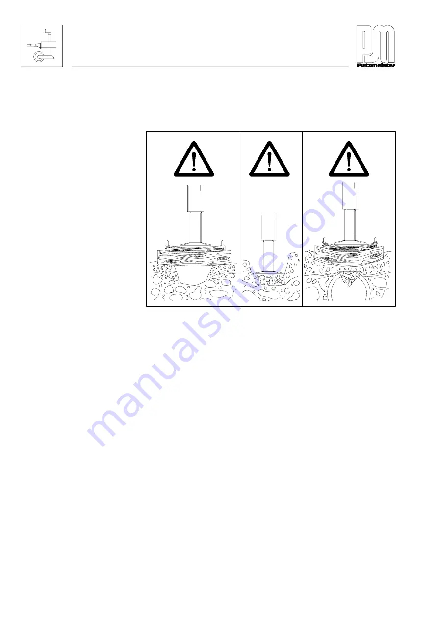
The  supporting  ground  must  be  firm  enough  to  absorb  the  forces
conducted  by  the  support  feet  into  the  ground.  There  must  not  be
any  voids  or  ground  unevenness  under  the  support  feet.

22102802

No  voids  or  ground  unevenness  under  the  support  feet

"

Always  rest  the  support  feet  on  support  plates,  timber  blocks
or  other  suitable  construction  timber.

It  is  recommended  that  you  select  a  set

up  site  which  has  been  con

creted  if  the  concrete  pump  is  to  remain  on  the  same  set

up  site  for

a  prolonged  period.

It  is  recommend  that  concrete  pumps  working  at  high

pressure  and

high  delivery  rate  are  securely  anchored.

Supporting ground

Summary of Contents for 210109379

Page 1: ...staff always keep by the machine Stationary concrete pump BSA 1005 D3B C Machine no 210109379 16 04 07 The paper on which this document is printed is 100 chlorine free E Putzmeister Concrete Pumps Gm...

Page 2: ...eister America 1733 90th Street Sturtevant WI 53177 USA 1 262 886 3200 1 262 886 3212 pmr putzam com www putzmeister com South Africa PMSA Putzmeister S A Pty Ltd Cnr Bramm Citrus St Honeydew P O Box...

Page 3: ...za uporabu hu Eredeti zemeltet si tmutat ford t sa it Traduzione delle istruzioni d uso originali lt Eksploatavimo instrukcijos originalo vertimas lv Lieto anas pam c bas tulkojums no ori in lvalodas...

Page 4: ......

Page 5: ...10 Manufacturer 2 2 2 1 11 Operator 2 2 2 1 12 Machine operator 2 2 2 1 13 Hoseman 2 2 2 1 14 Signaller and other auxiliary personnel 2 2 2 1 15 Truck mixer driver 2 3 2 1 16 Authorized inspector 2 3...

Page 6: ...uctions 2 16 2 6 2 Operating procedures 2 17 2 6 3 Other regulations 2 17 2 7 Personal protective equipment 2 18 2 8 Before starting work 2 20 2 8 1 Checking that the machine is ready for operation 2...

Page 7: ...uring delivery lines 2 40 2 13 3 Tightness and blockages 2 41 2 13 4 Opening delivery lines 2 42 2 13 5 Clearance to delivery lines 2 42 2 13 6 Fastening delivery lines 2 42 2 13 7 Continuation delive...

Page 8: ...ware 2 54 2 21 Protective and safety equipment 2 54 2 22 Electrical power 2 55 2 22 1 General 2 55 2 22 2 Electrical components 2 56 2 22 3 Power at the construction site 2 56 2 23 Hydraulic systems 2...

Page 9: ...3 12 3 4 5 Agitator 3 14 3 5 General conditions for using a concrete pump 3 15 3 5 1 Service life 3 15 3 5 2 Site of use 3 16 3 5 3 Height of job 3 16 3 5 4 Operating temperature 3 17 3 5 5 Centraliz...

Page 10: ...1 4 1 2 Functional fluids 4 2 4 1 3 Condensate water 4 3 4 1 4 Lubrication points 4 3 4 1 5 Hydraulic fluid radiator 4 3 4 1 6 Water box 4 4 4 1 7 Parts in contact with concrete 4 5 4 2 Test run 4 6...

Page 11: ...sis 5 4 5 1 5 F 25 chassis 5 4 5 1 6 F 80 chassis 5 5 5 1 7 Crawler track 5 7 5 1 8 Static base structure 5 7 5 2 Hand signals for driving 5 8 5 3 Requirements for the set up site 5 10 5 4 Setting up...

Page 12: ...ping 6 8 6 7 Pumping 6 9 6 7 1 Monitoring 6 10 6 7 2 Blockages 6 12 6 7 3 Breaks in pumping 6 13 6 7 4 Engine 6 14 6 7 5 Overheating 6 14 6 7 6 Restarting 6 16 6 8 Emergency operation pump function 6...

Page 13: ...3 1 Personal protective equipment 7 7 7 3 2 Personnel requirements 7 7 7 3 3 Auxiliary devices 7 7 7 3 4 Residual risks 7 8 7 4 General tightening torques 7 10 7 4 1 Set screws and nuts 7 10 7 4 2 Fl...

Page 14: ...bearing 7 49 07 070 Replacing the switching shaft bearing flanged bearing 7 55 07 071 Replace the spectacle wear plate 7 71 07 072 Replacing the S transfer tube 7 85 07 073 Replacing the S transfer t...

Page 15: ...ndex of key words Glossary G 1 Symbols for concrete pumps in accordance with German Mechanical Engineering Association Standard VDMA 24119 G 1 G 2 Key to the symbols for concrete pumps G 7 G 3 Abbrevi...

Page 16: ......

Page 17: ...se Operating Instructions Do not hesitate to contact us if you have any queries Putzmeister Condrete Pumps GmbH After Sales Department Max Eyth Stra e 10 D 72631 Aichtal Germany Telephone 49 7127 599...

Page 18: ......

Page 19: ...egulations for accident prevention and environ mental protection The Operating Instructions must always be available wherever the machine is in use These Operating Instructions must be read and applie...

Page 20: ...acturer apply for this Modifications are made from time to time in the interests of constant improvement and it could be possible that we were unable to take these into consideration when these Operat...

Page 21: ...ormal tools i e commercially available tools or tools carried in the truck are not specially listed Environmental protection Particular specifications regarding environmental protection are introduced...

Page 22: ...possible to identify the source of the danger precisely Danger of fire This icon is used to identify actions for which there is a particular danger of fire Danger of explosion This icon is used to id...

Page 23: ...with lethal consequences Danger of burning This icon is used to identify actions in which there is a danger of burning from chemical substances which are not specifically described Danger of burning T...

Page 24: ......

Page 25: ...asic instruction for new operators Note Special safety regulations may be necessary for some tasks These special safety regulations will only be found in the description of the particular task We incl...

Page 26: ......

Page 27: ...nsemble of placing boom and base structure For the purposes of this Safety Manual concrete pumps are defined as devices which are designed to deliver concrete to placement sites via pipes or hoses In...

Page 28: ...epresentative of the owner of the concrete pumps and or placing booms The operator is responsible for the use of these ma chines Person trained in and charged with the operation of concrete pumps and...

Page 29: ...ion in the work of an authorized inspector To possess thorough knowledge of the relevant health and Safety Manual as well as of directives and the generally recognised rules of engineering To have acc...

Page 30: ...ions 2 4 BP03_076_1601EN 2 1 21 Place of work working area danger zone ab0005 14 6 7 1 2 3 5 6 8 9 10 11 12 Example ab0010 14 1 1 2 3 3 4 4 5 6 6 8 9 11 11 12 13 13 10 13 Example Mobile machines Stati...

Page 31: ...8 At the end hose Risk of injury when pumping is started during pumping operations when removing a blockage and during washing out procedures The diameter of the danger zone is twice the end hose leng...

Page 32: ...hopper and at operating elements for the agitator and truck mixer This requires a greater level of caution The truck mixer driver and machine operator must have visual contact The working area is the...

Page 33: ...uck mixer driver If a workplace falls within the danger zone increased caution is required and suitable personal protective equipment is prescribed Persons who are authorized to be present in such a w...

Page 34: ...t The diameter of the danger zone is twice the end hose length In the area of the hopper there is a risk of becoming trapped be tween the truck mixer and the hopper and of being sprayed with concrete...

Page 35: ...itial commissioning of the machine the operational safety of the machine must be checked regularly by a subject expert The in spection intervals depend on the age of the machine The older the machine...

Page 36: ...ng hours meter records the hours of pumping operations The operating hours meter must always be kept in good working order It must not be tampered with For machines without an operating hours meter th...

Page 37: ...c The maximum permissible gross weight may not be ex ceeded The placing boom must never be used for lifting loads wz0006 The placing boom must not be used under any circumstances to re move obstacles...

Page 38: ...hose for example The quoted gross weight must not be exceeded If a longer end hose is used the diameter of the danger zone is also increased see also page 2 37 End hoses with a length of more than 4 m...

Page 39: ...be moved backwards beyond the vertical of the placing boom wz0026 It is prohibited to climb the placing boom to stand on top of it or to misuse it as a working platform or aid to climbing wz0037 2 3...

Page 40: ...facturer the warranty will be in validated in the following situations in particular use contrary to designated use incorrect operation maintenance and repair use of spare parts or accessories other t...

Page 41: ...ng parts All persons working on or with the machine must concentrate on the task at hand and not be distracted particularly by smartphones and music played through headphones Do not allow persons who...

Page 42: ...derstanding and application of the Operating Instructions and Safety Regulations and Safety Man ual At regular intervals of at least once a year check that personnel are conscious of safety and the ha...

Page 43: ...relating to accident prevention and environmental protection Such regulations may also deal with handling hazardous substances the issuing and wearing of personal protective equipment or with nationa...

Page 44: ...head against for instance falling concrete or parts of the delivery line in the event of a hose bursting DIN EN 397 Industrial safety helmets Safety footwear Safety footwear protects your feet against...

Page 45: ...ety harness When working at height use the climbing aids and working plat forms provided for reasons of safety or wear a safety harness The relevant national regulations must be complied with DIN EN 3...

Page 46: ...flame when handling fuel Set all the control and monitoring devices to the zero position before you change the mode of control control block control console or remote control Press the EMERGENCY STOP...

Page 47: ...outside in this discharge voltage pat tern If you step within this discharge voltage pattern you will bridge different potentials This will cause a voltage corresponding to the potential difference to...

Page 48: ...he unfolded placing boom if you wish to estimate correctly the movements of the boom and above all the clearance between the placing boom and obstacles or high voltage lines The same minimum clearance...

Page 49: ...can occur despite the use of a high voltage warning device You must therefore always maintain the minimum clearances mentioned above Should a flash over occur despite all precautions stay calm do not...

Page 50: ...n the vicinity of transmitters radio transmitter etc Persons who bridge the charged parts to the earth are heavily charged on con tact Machines in use in the vicinity of transmitters must be earthed S...

Page 51: ...t conditions may change as construction work prog resses Please also observe section 2 11 1 Mobile machines set up site Stationary booms can be erected on tubular columns lattice booms or other base s...

Page 52: ...hat the assembled machine is working properly Only use suitable means to load and transport stationary machines Ensure that no one can be injured by the machine tipping over or slipping If there are t...

Page 53: ...adequately lit Do not park the machine in areas where equipment may fall down Incidents of overlapping with the working areas of other machines particularly cranes other placing booms etc should be a...

Page 54: ...un even ground The support area must be enlarged as required Support blocks and timber blocks may be used to increase the support area The sup port timbers must be undamaged and free from ice oil gre...

Page 55: ...ngle of 45_ Safe clear ance to the pits and slopes must be maintained and such clearance must be determined in accordance with the nature of the ground The safe clearance is measured from the foot of...

Page 56: ...nding notes in this regard in the operating instructions Do not carry out more than one movement at a time If a movement is stopped the entire volume of fluid is available for the remaining movements...

Page 57: ...erload the slewing gear for the placing boom as well as its overall support structure jeopardising the stability of the machine wz0106 Check stability regularly during operation The elastic distortion...

Page 58: ...wed secured The maximum permissible gross weight may not be exceeded While the vehicle is being driven the delivery line pump and hopper must be empty If there are concrete leavings in the hopper it m...

Page 59: ...to a lower gear on a slope but always before reaching it Observe national road traffic regulations If necessary clean the tyres lights and number plate Before travelling with the machine check that t...

Page 60: ...Use only appropriate means of transport and lifting equipment of ad equate loadbearing capacity Lifting equipment lifting tackle sup port trestles and other auxiliary equipment must be reliable and s...

Page 61: ...ng out several movements at once requires an increased level of attentiveness The range of a radio remote control is great enough for the machine to receive control commands e g from a great distance...

Page 62: ...rea This high ma noeuvrability means different placing booms can also be moved into dangerous positions Prohibited areas can be found in the Operating Instructions There is a risk that you will damage...

Page 63: ...ngth Do not guide the end hose when pumping is started There is a risk of injury from the end hose swinging out or stones being ejected wz0136 If a longer end hose is used the diameter of the danger z...

Page 64: ...concrete and so that concrete is directed pre cisely into the site of concrete placement Control the placing boom so that the hoseman can guide the end hose without power consumption The hoseman must...

Page 65: ...is a risk of lightning strike Tower cranes on construction sites generally have wind speed measuring equipment so that you can ask about the wind speed at any time If no wind speed measuring equipment...

Page 66: ...een ap proved by the machine manufacturer Delivery lines are subject to wear which varies according to the pressure and composition of the concrete the material from which the delivery line is made et...

Page 67: ...e e g by increasing the delivery pressure using compressed air etc There is a risk of fatal injury from the delivery line bursting or from concrete being ejected from the end of the delivery line Prev...

Page 68: ...pumping operations Cordon off the danger zone If it is not possible to place a large enough cordon around the danger zone the deliv ery line must be covered by suitable means Delivery lines in particu...

Page 69: ...riven devices are generally supplied with power by a machine s hydraulic system It must therefore be poss ible to see from the devices and the machine with control unit and vice versa Observe the Safe...

Page 70: ...o will not endanger anyone s safety Refrain from any procedures that may impair the stability of the ma chine or are prejudicial to safety in any other way You must always carry the remote control on...

Page 71: ...en hit you or be torn from your hands and cause you injury You should be constantly observing the machine for any damage or faults while it is in use In the event of faults or malfunctions that im pai...

Page 72: ...d support legs must be fully retracted and secured wz0156 The preferred methods for cleaning the delivery line are reverse pumping or forced cleaning with water The agitator must be switched on during...

Page 73: ...e hose It could become entangled with moving machine components Take care when using aggressive cleaning agents Aggressive cleaning agents may attack materials e g rubber and painted sur faces You can...

Page 74: ...ughout their length Reducer pipes must be drained and flushed out by hand No bends delivery or end hoses may be fitted at the end of the delivery line A catch basket must be fastened at the end of the...

Page 75: ...mpletely The dump cock must be opened in such a way that no one can be injured by concrete residue that might be expelled from the dump cock Water spraying on the machine from random directions has no...

Page 76: ...olutely necessary for the execution of maintenance work Secure a wide area around the maintenance area as far as is necessary A machine completely shut down for maintenance and repair work must be sec...

Page 77: ...ined for such work Clean the machine especially connections and threaded unions of any traces of oil fuel or preservatives before carrying out mainten ance or repair work Do not use aggressive cleanin...

Page 78: ...arc welding processes For this reason Disconnect the remote control cable from the control console Disconnect all cables leading to the receiver of the radio remote control system Close connector soc...

Page 79: ...ew delivery line will have to be redetermined using special equip ment Following substantial changes placing booms must be inspected by an authorized inspector before recommissioning Some of the manuf...

Page 80: ...d for maintenance purposes must be refitted and checked immediately upon completion of this work All equipment required for safety and accident prevention warning signs and information plates grilles...

Page 81: ...te adjacent live parts Disconnect the negative lead from the battery before starting any work on the electrical system of machines with an internal combus tion engine When reconnecting connect the pos...

Page 82: ...power supply The power on the construction site must be supplied from a special feed point construction site power distribution point Machines with an electric motor must not be connected to the main...

Page 83: ...o be opened hy draulic pneumatic and delivery lines must be depressurized ac cording to assembly descriptions before repair work is started Work only on depressurized systems Switch the hydraulic pump...

Page 84: ...etest must be recorded in the check book The operator must have hydraulic hoses replaced if they show signs of external damage The place of work in normal operation is with the remote control For this...

Page 85: ...material When handling oils greases and other functional fluids observe the Safety Manual applicable to the product concerned see the safety data sheet Oils fuel and other functional fluids may be ha...

Page 86: ...To dispose of the machine you must proceed in accordance with all points in the disposal regulations which apply in your country During the disposal operation you must observe the following in partic...

Page 87: ...n This chapter describes the components and assemblies on this machine and describes how they function Please note that available options will also be described The machine card will tell you whether...

Page 88: ......

Page 89: ..._050_1603EN 1 1 2 3 4 5 6 8 7 9 9 10 11 12 Pos 0 Component Page 1 Documentation accompanying the machine 2 Engine 3 Hydraulic pumps 4 Pressure filter 3 77 5 Hydraulic fluid reservoir 6 Fuel tank 7 Vib...

Page 90: ...Page 1 Output controller 3 75 2 OPS SPC control cabinet 3 21 3 Magnetic switch distributor casing 3 69 4 Cable remote control 3 63 5 Machine rating plate 3 7 6 Battery 7 Fuse box 3 62 Control block 8...

Page 91: ...ton STOP button on the remote control 2 Covers over the switch cylinders 3 Side protection doors 4 Exhaust guard 5 Safety grille on the V belt 6 Transport protection 7 Securing bolts spring pins on th...

Page 92: ...equipment 14 Sound proofing equipment sound proofing kit 15 Spray guard 16 Grille on the hopper Danger Never operate the machine if the safety equipment is not working You could injure yourself or ot...

Page 93: ...110x63 Performance data Main pump hydraulic fluid pressure 280 bar 280 bar Maximum concrete pressure rod side bar 70 bar Maximum concrete pressure piston side 55 bar bar Maximum output rate rod side...

Page 94: ...ndividual tests Basic standard System Requirement Result Emission ra diated interfer ence SA EN 13309 2000 Radio interference field intensity EN 13309 2000 30 1000 MHz Broadband A 1 Narrow band A 3 pa...

Page 95: ...fluid pressure in the hydraulic system bar 5 Year of manufacture 6 Maximum delivery pressure bar The following data depend on the machine model 7 Total weight kg 8 Delivery line diameter mm Note If sp...

Page 96: ...he vicinity of the machine since the sound pressure level can be higher The sound pressure was determined on the basis of Directive 2000 14 EU The sound power level produced by the machine is given be...

Page 97: ...given in dB A Disadvantage the actual sound pressure level is higher if you stand closer to the machine Nowadays the sound power level of the machine is stated To calcu late this an imaginary sphere o...

Page 98: ...ne can be towed by a tractor unit if fitted with an F 8 chassis The chassis is unbraked and is designed for a maxi mum speed of 8 km h only The machine may therefore only be towed by a tractor unit on...

Page 99: ...a tractor unit if fitted with a crawler track Note Observe the manufacturer s operating and maintenance instructions The machine is neither equipped nor approved for travel on public roads If your ma...

Page 100: ...iven hydraulically by diesel engines or electric motors acting through fluid pumps The delivery pistons 3 are connected to the piston rods 1 of the drive cylinders by way of intermediate flanges The d...

Page 101: ...piston forces the medium which has previously been sucked in through the transfer tube into the delivery line At the end of the stroke the pump switches over i e the transfer tube is swung in front o...

Page 102: ...on 1 Hydraulic motor 2 Agitator shaft 3 Agitator helix The filling rate in the delivery cylinders should be as high as possible when pumping This is achieved by having the agitator helix mix to wards...

Page 103: ...ent spare parts and accessory components are used the service life is 15 years Truck mounted concrete pump standard Output m3 year 30000 Operating hours h year 400 Uses per day 3 Uses per year 750 Tru...

Page 104: ...ve atmosphere Putzmeister must be contacted if the concrete pump is to be used at a height greater than that given here The standard reference level is the European standard elevation zero NHN Pump ty...

Page 105: ...piston pump 15 50 Stationary concrete pump with diesel engine 8 45 Stationary concrete pump with electric motor Stationary boom 8 40 General rotor pump 3 40 Limited due to the diesel engine without p...

Page 106: ...ief valves and supply lines AP02_908_1304EN 1 1a 3 5 1b 2 3 4 4 7 7 9 6 8 No 0 Designation 1a Lubricant reservoir 1b Lubricant pump 2 Grease gun 3 Lubricant distributor 4 Agitator shaft bearings 5 Tra...

Page 107: ...king through the filling nipple or from above through the filling opening Note Note the following when filling the lubricant reservoir Use only a grease listed in the lubricant recommendation table Ne...

Page 108: ...bols used on the electrical con trol devices are described in one of the preceding sections The electrical control devices may include the following components depending on the equipment on your machi...

Page 109: ...erating elements illustrated below may not be present on your machine The hole is closed with a blanking plug if a control or operating element is omitted AP21_022_1510EN 1 1 2 3 4 5 6 7 8 9 10 11 Pos...

Page 110: ...agitator safety cutout RSA 7 Ignition starter switch Diesel engine On Off 8 Toggle switch Open shut off valve agitator close shut off valve 9 Toggle switch Agitator on agitation direction away from th...

Page 111: ...22_1510EN 2 1 2 Pos 0 Operating control element Meaning function Comments 1 Round socket 4 pin Connection for vibrator optional 2 Socket Connection for remote control Local control Remote control Loca...

Page 112: ...in the SPC display 2 Momentary contact switch Function button for navigation and operation 3 System LED The LED of the display unit lights up when the control cabinet is supplied with power and flash...

Page 113: ...gain using the Forward pumping 0 Re verse pumping toggle switch The control system can control machines with an open hydraulic cir cuit The open hydraulic circuit is called Open Pump System OPS For di...

Page 114: ...EMERGENCY STOP circuit is activated automatically when you remove the replacement plug remote control You must press the Deactivate EMERGENCY STOP toggle switch to deactivate the EMERGENCY STOP circui...

Page 115: ...3 6 Pos 0 Operating control element Meaning function 1 SPC display Menu driven operating states and adjustable functions are displayed in the SPC display 2 Button Function button for navigation and o...

Page 116: ...on the engine s control dis play Limit reached Red Warning on the engine s control dis play Fault The fault must be remedied before the operation can be restarted on the machine Dark grey Display of i...

Page 117: ...ption 3 29 AP21_045_1602EN The following pages show the password free section of the menu structure example A start screen is always displayed when the machine is started up AP21_045_1602EN 1 1 2 3 4...

Page 118: ...tware information Select this menu to display the software version and firmware version 3 45 5 Operating data Select this menu to display operating data 3 46 6 Fault memory Select this menu to display...

Page 119: ...ce the power supply or the engine of the stationary concrete pump is switched off Note Depending on the equipment fitted to your machine some of the functions illustrated may not be present The symbol...

Page 120: ...y pressing button 1 2 Button The expanded HOME menu is opened by pressing button 2 in the HOME menu 3 Direction key Submenus are selected by pressing on the left or right of the direction button 3 4 B...

Page 121: ...ack to the start menu This symbol is displayed regardless of the current menu The symbol has no function in the HOME menu 2 Menu Expanded HOME Submenu Software information Submenu Operating data Subme...

Page 122: ...4 AP21_046_1602EN Continued Pos 0 Symbol Function meaning 1 Switch EOC on off 2 S transfer tube switch over Snail hare and auto 3 Reset the trip day counter This symbol is displayed in the following m...

Page 123: ...3 2 3 Pos 0 Display Function meaning 1 Cooling water temperature C analogue and digital The cooling water temperature is displayed 2 Engine speed rpm analogue and digital The engine speed is displayed...

Page 124: ...ion 3 36 AP21_047_1602EN Symbols in the HOME menu AP21_047_1602EN 1 Note Depending on the equipment fitted to your machine some of the functions illustrated may not be present The symbol is not lit if...

Page 125: ...s symbol flashes and is displayed in red if the engine oil tempera ture specified by the engine manufacturer is exceeded If the signal for the engine oil temperature is interrupted for longer than a f...

Page 126: ...fault has occurred in a magnetic switch or resolver You need to have the fault rectified by a Putzmeister service technician Hydraulic fluid overheating This symbol is displayed in grey if the temper...

Page 127: ...nd all pump functions Pump on Forward pumping and Reverse pumping either have not been operated or have been acknowledged This symbol is displayed in white if the concrete pump is switched off when th...

Page 128: ...ed in numbers if the concrete pump is switched on and the Forward pumping pump function is operated S transfer tube switch over The S transfer tube switch over function can be switched over as follows...

Page 129: ...t the Pump off 0 Vibrator on toggle switch has been switched to Vibrator on on the control cabinet with SPC display This symbol is displayed in green if the vibrator is switched on Lubrication This sy...

Page 130: ...y pressing button 1 2 Button The HOME menu is opened by pressing button 2 in the expanded HOME menu 3 Direction key Submenus are selected by pressing on the left or right of the direction button 3 4 B...

Page 131: ...played 2 Engine oil pressure bar analogue The engine oil pressure is displayed 3 Engine speed rpm ana logue and digital The engine speed is displayed 4 Hydraulic fluid tempera ture C analogue The hydr...

Page 132: ...n find a description of all symbols in the menu bar regardless of the current menu in the section All symbols in the menu bar Symbols in the expanded HOME menu AP21_029_1511EN 3 Note You can find a de...

Page 133: ...aning PM Putzmeister SPC Small Pump Control g2 Generation 2 C Controller D Display V100 Version 1 0 0 1 AP21_030_1511EN 1 2 Pos 0 Display Function meaning 1 Software versions The software versions of...

Page 134: ...ht AP21_031_1511EN 1 1 2 10 9 8 7 6 5 4 3 Pos 0 Display Function meaning 1 Total table The total values for the operating data are displayed 2 Trip table The current values for the operating data are...

Page 135: ...r box 6 Stroke time 1 s The current stroke time 1 is displayed Stroke time 1 For example the time required for drive piston 1 to move towards the cylinder base 7 Delivery rate m3 The current delivery...

Page 136: ...ault codes for the most recent faults are displayed in this menu 1 AP21_032_1511EN 1 2 Pos 0 Display Function meaning 1 Fault The fault code is displayed 2 Momentary contact switch The last selected H...

Page 137: ...g data specified above In exceptional cases where there is no information between the en gine and the controller you can perform a simulation of the engine speed If a fault has occurred in a magnetic...

Page 138: ...on key Parameters are selected by pressing up or down on the direction button 2 The value of the parameter is set by pressing left or right on the direction button 2 3 Momentary contact switch The set...

Page 139: ...is displayed 2 Actual value adjustable The pump output or fill level of the delivery cylinders that has been achieved is displayed The two parameters are used in the calculation of the output m3 h 3 I...

Page 140: ...the stroke time are displayed 6 In the event of a fault Engine speed rpm digital The simulated engine speed is displayed in numbers 7 Fill level of the delivery cyl inders The setpoint and actual val...

Page 141: ...e lubrication menu AP21_048_1602EN 1 1 2 3 4 5 Pos 0 Display Function meaning 1 Button The last selected start menu is opened by pressing button 1 2 Button A manual lubrication cycle is activated by p...

Page 142: ...the menu bar AP21_048_1602EN 2 1 2 3 Pos 0 Symbol Function meaning 1 Back to the start menu This symbol is displayed regardless of the current menu The symbol has no function in the HOME menu 2 Manua...

Page 143: ...trokes until the next lubrication is displayed 2 Number of strokes digital The number of strokes until the next lubrication is displayed in numbers 3 Number of strokes digital The number of strokes pe...

Page 144: ...he S transfer tube for example after installing the resolver Function buttons in the inputs and outputs menu AP21_049_1602EN 1 1 2 Pos 0 Display Function meaning 1 Button The last selected start menu...

Page 145: ...e menu bar AP21_049_1602EN 2 1 2 Pos 0 Symbol Function meaning 1 Back to the start menu This symbol is displayed regardless of the current menu The symbol has no function in the HOME menu 2 The positi...

Page 146: ...unction meaning 1 IN inputs analogue An overview of all inputs is displayed The active inputs are displayed in green 2 IN inputs digital The active inputs are also displayed in numbers 3 OUT outputs a...

Page 147: ...e selected engine speed You can switch the Ergonic Output Control on and off using the SPC display unit HOME menu AP21_034_1512EN 1 1 Pos 0 Display Function meaning 1 Symbol EOC 2 Momentary contact sw...

Page 148: ...s started up is smaller than the saved EOC speed The engine will run with no change in speed if the current engine speed when the concrete pump is started up is greater than or equal to the saved EOC...

Page 149: ...et engine speed The engine will run with no change in speed if the current engine speed when the concrete pump is started up is greater than or equal to the factory set engine speed The engine speed c...

Page 150: ...time AP02_933_1309EN 1 1 2 No 0 Operating control element Meaning function 1 Fuse box 2 Toggle switch Engine protection override Special features of the fuse box If the engine overheats it switches o...

Page 151: ...contact switch EMERGENCY STOP 2 Toggle switch Increase speed Reduce speed 3 Toggle switch Deactivate EMERGENCY STOP 4 Toggle switch Pump On 0 Reverse pumping Note You need only press one of the EMERGE...

Page 152: ...the green Pump running indicator lamp flashes if you have pressed the EMERGENCY STOP button You can only restart the pump as described below Unlock the EMERGENCY STOP button by turning it Operate the...

Page 153: ...the positions of the EMERGENCY STOP but tons on your machine 30505901 EMERGENCY STOP button Note You need only press one of the EMERGENCY STOP buttons to trigger an EMERGENCY STOP of the machine To re...

Page 154: ...in pumps swing back the delivery pistons come to a halt the change over valve is disconnected Note If the machine has an electrical agitator safety cutout the accumula tor dump valve is opened and the...

Page 155: ...witch over In addition the delivery pistons return to the end position and the concrete pump halts You must switch the concrete pump off and back on again to restart it In order that the agitator star...

Page 156: ...e always check that the agitator safety cutout is working properly before using the pump The LED on the evaluation device has the following display The green LEDs flash for 8 seconds during the initia...

Page 157: ...3_1202EN 1 1 3 2 4 5 No 0 Control element Meaning Function Belongs with no 1 Yellow LED Magnetic switch rod side drive cylinder II 2 Yellow LED Magnetic switch rod side drive cylinder I 3 Female conne...

Page 158: ...me time LED for magnetic switch Magnetic switch status lights up briefly on switchover Magnetic switch is OK does not light up despite triggering Magnetic switch connector or lead are defective replac...

Page 159: ...down If the time has elapsed the rod side magnetic switch in drive cylinder 2 is cleared This means that switchover only occurs through the piston side magnetic switch in drive cylinder 1 Once this ha...

Page 160: ...ing diode These LEDs indicate the status of the connector and the magnetic switch 20500406 2 3 1 No 0 Designation 1 Green and yellow LEDs 2 Connector 3 Magnetic switch Note The yellow LED indicates th...

Page 161: ...pportunity lights up continuously Magnetic switch is defective remove connector from the magnetic switch otherwise switchover is not possible and replace at earliest opportunity Green LED Connector an...

Page 162: ...on the hydraulic control devices are described in one of the preceding sections The hydraulic control devices may include the following components depending on the equipment on your machine agitator...

Page 163: ...ustment valve so that the output is increased or reduced If the output controller 1 shows min the delivery cylinders remain stationary the concrete pump is switched off AP21_010_1505EN 1 1 Operate the...

Page 164: ...EN 1 No 0 Designation 1 Emergency operation transfer tube 2 Drive cylinder emergency operation Special features of the pump control system In the event of a control system failure you can switch the t...

Page 165: ...e gauge AP02_063_0308EN 1 The condition of the suction filter can be seen on the vacuum meter that of the pressure filter can be seen directly on the filter housing AP02_063_0308EN 2 Vacuum meter AP02...

Page 166: ...ther components are described in one of the preceding sections The following components may be described here depending on the equipment on your machine manual throttle lever for the engine flushing w...

Page 167: ...hydraulic fluid radiator fan is hydraulically powered and runs once the machine is switched on The hydraulic fluid radiator cools the diesel engine and the hydraulic fluid circuit of the concrete pump...

Page 168: ...ularly in the case of very stiff concrete The vibrator is electrically driven the connecting plug must be plugged into the appropriate socket on the control cabinet for this to work 31201000 1 2 3 4 N...

Page 169: ...the first time and how to prepare your machine for use if left idle for a prolonged period Information is available on how to check your machine and how to carry out a test run with visual and functio...

Page 170: ......

Page 171: ...sibility for the safety of anyone located in the machine s danger zone You are therefore under an obligation to ensure that the machine is com pletely safe in operation The fundamental prerequisite fo...

Page 172: ...ou must therefore always wear personal protective clothing and equipment when you are handling toxic caustic or other functional fluids that are injurious to health and always take note of the manu fa...

Page 173: ...under the drain cock to catch the escaping condensate water Open the drain cock Close the cock again as soon as fluid runs out Check that all lubrication lines are tight and free from fracture Check...

Page 174: ...ly covered Check the water condition The drive cylinders are leaking if there is a clearly visible escape of fluid particularly at the piston rods At least one of the delivery pistons is worn if the a...

Page 175: ...he inner wall of the pipe and its thrust ring for wear Reconnect the delivery line bend to the pressure connection Look into the hopper and check on the condition of the spec tacle wear plate and the...

Page 176: ...with the machine running Caution The ventilation flap must be open before you switch on the machine All operating and control elements on the control cabinet in particu lar the main switch and the EM...

Page 177: ...chapter entitled Transport setting up and connection The engine can only be switched on when it is under no load i e there must be no consumers switched on Switch the agitator off Turn the Increase R...

Page 178: ...al control replacement connector Switch on the diesel engine using the ignition starter switch The SPC Display lights up Actuate the Deactivate EMERGENCY STOP toggle switch on the control cabinet Swit...

Page 179: ...d positions of the output controller AP13_026_0510EN 1 Checking the magnetic switches Check that the drive cylinders switch over automatically once the hydraulic pistons are close to the magnetic swit...

Page 180: ...et the maximum pumping rate Start the measurement at the first switch over of the transfer tube The first single stroke is complete with the next transfer tube switch over Measure the stroke time over...

Page 181: ...e able to switch off the machine quickly enough if danger threatens You must therefore check the functioning of the EMERGENCY STOP buttons each time you start work 10500200 Press lock EMERGENCY STOP T...

Page 182: ...transfer tube is switching A defective agitator safety cutout can cause you to believe that the machine is safe even though this is not really the case This can lead to the agitator continuing to run...

Page 183: ...inet 4 Reading head on the hopper example illustration Open the grille with the concrete pump running The transponder signal is broken The agitator must come to a halt immediately The transfer tube mu...

Page 184: ...and the transfer tube is switching A defective agitator safety cutout can cause you to believe that the machine is safe even though this is not really the case This can lead to the agitator continuing...

Page 185: ...202EN AP13_076_1202EN 1 1 No 0 Designation 1 Acknowledge agitator or agitator safety cutout on the EPS EGD control cabinet Actuate the Acknowledge agitator or agitator safety cutout toggle switch on t...

Page 186: ...e maximum pumping rate Note The indicators on the filters can only be checked under load once the hydraulic fluid has warmed up Please read the Filter change maintenance card 10300200 Vacuum meter Not...

Page 187: ...filter if it is sticking up Note You must replace the filter element if the red button pops out again after a short time The filter is OK if the red button remains depressed Environmental protection...

Page 188: ...1a 1b AP13_110_1511EN 1 No 0 Designation 1 Agitator On agitation direction away from the delivery cylinder 1a Agitator Off Agitator On agitation direction towards the delivery cylinder 1b Actuate the...

Page 189: ...lectrical connection must first be made between it and the control cabinet 31201000 1 2 3 4 Check that the vibrator is functioning correctly Note The vibrator will only function when the switch for th...

Page 190: ...owing tasks Switch off the pump at the control cabinet Switch off all power consumers Switch off the engine at the control cabinet Switch the main switch off The Ready for Service indicator lamps go o...

Page 191: ...P06_001_1007EN 5 Transport setting up and connection This chapter contains information relating to transporting the ma chine Tasks required for setting up and connecting the machine are also described...

Page 192: ......

Page 193: ...eyes will need to be fitted to the machine should you wish to load it onto a transport vehicle Any lifting eyes fitted to your machine for the purpose of lifting it will be located on the top of the m...

Page 194: ...e machine standing on its support legs so that it cannot roll away AP06_003_1007EN 1 1 Suspend by all lifting eyes 1 Rope angle 45_ Hook a four cable sling to the 4 lifting eyes Danger The machine may...

Page 195: ...AP06_003_1007EN Suspended load Use only appropriate lifting gear Suspend the BSA from the lifting eyes specified Never hoist the load over people Take note of the safety regulations for crane operatio...

Page 196: ...icted to the construction site or private property Caution The machine must not exceed a maximum speed of 8 km h when under tow if fitted with an F 8 chassis You must load the machine onto a suitable...

Page 197: ...ver of the tractor unit must have the relevant driving licence If you have to drive in reverse you must always ask for a signaller to guide you If necessary have the route cordoned off or secured by a...

Page 198: ...is safe to drive lighting brakes tyre inflation pressures wheel nuts etc Clean the machine so that it does not soil the public roads Check that the accessories are secure Danger Supports extending sp...

Page 199: ...ope and on ascending or descending routes You must load the machine onto a suitable transport vehicle to trans port it to the construction site see Loading Your machine can be towed by a tractor unit...

Page 200: ...must be agreed between signaller and machine operator Below you will find some suggestions for hand signals to be used when driving Extend both arms out to the side 10000306 With the arm crooked point...

Page 201: ...the direction the truck should drive 10000303 With the arm crooked wave the palm in the direction the truck should drive 10000304 With the arm crooked indicate the distance to an obstacle with the pa...

Page 202: ...neration procedures stationary regener ation are regularly triggered automatically or if required activated manually Danger of fire Danger of fire due to inadequate clearance from a stationary con cre...

Page 203: ...n all the guards flaps and hoods without obstruction Ensure that there is sufficient clearance around the entire ma chine The approach route must be sufficiently firm that so it can be driven over reg...

Page 204: ...2102802 No voids or ground unevenness under the support feet Always rest the support feet on support plates timber blocks or other suitable construction timber It is recommended that you select a set...

Page 205: ...f up to 12 tons is 1 metre Maintain a distance from pits slopes trenches etc when ap proaching the set up site The set up site must be adequately illuminated in order to ensure safe working on the mac...

Page 206: ...rements for the set up site Drive the machine to the inspected set up site AP06_070_1403EN 1 1 2 2 Initial situation Pos 0 Designation 1 Support wheel 2 Support leg with support foot Use chocks to sec...

Page 207: ...Transport setting up and connection 5 15 AP06_070_1403EN AP06_070_1403EN 2 Lowering the drawbar at the front Wind up the support wheel in order to lower the drawbar...

Page 208: ...suitable material beneath the rear support feet Unlock the rear support feet by removing the spring pins from the locking bolts and then removing the bolts Extend the rear support feet until the mach...

Page 209: ...be extended to exactly the same extent as the rear feet Place timber blocks or other suitable material beneath the for ward support feet Unlock the forward support feet by removing the spring pins fro...

Page 210: ...the machine is supported Note Sudden pulsations from the delivery line may be transmitted to the machine under extreme operating conditions e g high pressure delivery These pulsations could jeopardis...

Page 211: ...d on the pump rating plate The delivery lines are subject to wear which is dependent upon the concrete pressure the concrete composition the delivery line material AP06_014_1007EN 1 10 9 8 7 5 4 3 2 6...

Page 212: ...uries may be caused by the delivery line bursting as a re sult of a sudden increase in pressure Do not remain in the danger zone of a stationary delivery line Cover the stationary delivery line with a...

Page 213: ...hout stresses Support the delivery line so that couplings can be easily fitted and removed Double wooden chocks see illustration are most suitable as they allow for longitudinal and latitudinal moveme...

Page 214: ...e to the pump and vice versa Guide the delivery line in the direction of the arrow away from the concrete pump The operator s side of the concrete pump is then not in the danger zone Fit only as new d...

Page 215: ...nary delivery line to reinforcements or scaf folding as these can be moved and could collapse If you wish to secure the stationary delivery line to reinforcements or scaffolding check whether the scaf...

Page 216: ...e with a delivery pipe secured to it or sealed inside it It takes pump pulsa tions from the delivery line Install a fixed point near to the concrete pump The pump pulsations are reduced and the delive...

Page 217: ...wnwards must always be fastened to the structure or background so that they are self supporting The delivery line must not be supported by the lowest pipe bend AP06_014_1007EN 8 Fastening the delivery...

Page 218: ...livery line can be closed off so that the pressure bears on the gate valve and not on the concrete pump The delivery line is called a downpipe if it is laid in such a way that the concrete is pumped d...

Page 219: ...een the individual pipes Note Grease all couplings and seals well internally before assembly Use a lithium soap base multipurpose grease with the marking K2K 4 mm AP06_014_1007EN 9 Putzmeister SK deli...

Page 220: ......

Page 221: ...AP07_026_9710EN 6 Pumping operations This chapter contains information regarding the operation of the machine for pumping You will learn what steps are required for pumping and cleaning...

Page 222: ......

Page 223: ...machine is functioning the delivery line is designed to withstand the relevant concrete pressure and the delivery line is correctly laid Note If a malfunction occurs during the pumping operation you m...

Page 224: ...the machine is ready for operation If this is unavoidable in exceptional cases you must switch off the remote control disconnect it and lock it away Danger Risk to life from unintended machine movemen...

Page 225: ...ngable acoustic signals such as a horn two way radio field telephone etc optical signals such as light signals hand signals etc a combination of optical and acoustic signals Suggestions for the most i...

Page 226: ...r it 10000327 The thumb of one hand points downwards The palm of the other hand is held under it 10000328 The crooked elbow of one arm points downwards into the palm of the other hand 10000329 Grip bo...

Page 227: ...ime as otherwise you will have to bleed the fuel line to the diesel engine Fill the fuel tank with commercially available branded diesel fuel only as otherwise the diesel engine can be damaged Use sum...

Page 228: ...ciency of the pump i e the output per stroke 11000401 1 2 3 No 0 Description 1 Aggregate 2 Cement paste 3 Boundary layer Note A low fill level will be achieved in the delivery cylinder if the consist...

Page 229: ...angerous as the compressed air is released suddenly at the end of the delivery line and the concrete can be blown out explosively No air must be sucked in for this reason You should therefore always f...

Page 230: ...ns 11000501 Starting pumping with thin concrete Insert two sponge balls into the delivery line through the wash out port Pour approximately 0 5 m3 thin concrete into the hopper Switch the agitator on...

Page 231: ...g admixtures must be mixed in for at least 4 minutes after they are added Pour the concrete from the truck mixer silo etc into the agitator hopper Switch the agitator on Begin delivery Note Start with...

Page 232: ...ressure gauge Check all displays for the monitoring instruments Vacuum meter the indicator must not be in the red zone An indi cator in the red zone implies that the associated vacuum filter is contam...

Page 233: ...a fault is indicated All faults must be rectified immediately otherwise the guarantee will be invalidated Check the bearings and seals on the switching shaft the pres sure connection and the agitator...

Page 234: ...lines are leaking leavings in the transfer tube and delivery line unsuitable concrete composition segregated concrete set concrete Caution In the event of blockages pump the concrete immediately back...

Page 235: ...r retentivity tendency to bleeding as the vibrations can segregate the concrete You must always leave the pump switched to reverse pumping when you begin pumping again and wait for the transfer tube t...

Page 236: ...operation under high load high ambient temperatures too little fluid in the hydraulic system dirty hydraulic fluid radiator insufficient radiator ventilation hydraulic fluid radiator sucking in hot ex...

Page 237: ...sary you can cool the drive cylinders with a water jet if the measures described above are not adequate 10600400 Direct the water jet at the drive cylinders and piston rods for the drive cylinders Cau...

Page 238: ...the radiator must remain in operation Refresh the water in the water box Wait until the fluid has cooled if you are not able to find the fault immediately Once the red indicator lamp has extinguished...

Page 239: ...the location of the pump control system refer to the overview at the start of the chapter General technical description Familiarize yourself with the functions of the pump control system by reading th...

Page 240: ...n 2 In order to be able to switch over the transfer tube keep the drive cylinder emergency operation 2 pressed while at the same time operating the transfer tube emergency operation 1 Note Press and h...

Page 241: ...s of your machine you must observe the following Never use sea water or other water containing salt for cleaning purposes You must rinse off any sea water that is deposited on the machine Do not use a...

Page 242: ...e recommend that you use the Putzmeister Leavings sheet to allow you to make use of the concrete leavings You can lay this down under the hopper before opening the hopper flap The con crete then flows...

Page 243: ...hing or loss of limb by shearing if you reach inside It is prohibited to reach through the hopper flap into the hopper from below AP07_040_1009EN 1 Do not reach into the hopper Compressed air cleaning...

Page 244: ...o clean the delivery line and the concrete pump directly the site use is completed 10003401 1 2 3 4 1 Sponge pig 2 Sponge cube 3 Sponge ball 4 Wash out pig You will need sufficient numbers of sponge b...

Page 245: ...elivery line Danger A catch basket on the end of the delivery line is an absolute require ment if you are forcing the concrete out using compressed air as otherwise there is a risk of injury from the...

Page 246: ...ete pump The cleaning connection can only be used for cleaning up to a maxi mum water or air pressure of 10 bar A catch basket on the end of the delivery line is an absolute require ment if you are fo...

Page 247: ...quickly It traps the wash out sponge in suction cleaning AP07_041_9712EN 1 1 2 1 T delivery pipe with wash out port 2 Wash out port lid Danger Make sure that the T delivery pipe is also designed for...

Page 248: ...oncrete flushing the concrete out and causing blockages 10003501 Rolled up cement bags Roll up 1 2 empty cement bags together Immerse the rolled up cement bags in water for about 5 minutes before star...

Page 249: ...ystem includ ing the accumulator fully depressurized when you are measuring the hose length required as otherwise there is a risk of injury as the transfer tube switches over AP07_041_9712EN 2 1 1 Adh...

Page 250: ...ack by the concrete pump from the site of concrete placement into the hopper Cleaning is backwards from the site of concrete place ment to the hopper The delivery line has been disconnected from the c...

Page 251: ...elivery line Leavings from to Method of cleaning Compressed air Horizontal line Water under pressure Suction cleaning Compressed air only with special Riser Water under pressure special equipment Suct...

Page 252: ...ng a water soaked wash out sponge Push a water soaked wash out sponge cube into the end of the delivery line at the site of concrete placement Switch the pump to reverse pumping The concrete and the w...

Page 253: ...wash out sponge has passed the point at which you are tapping AP07_043_9712EN 2 Turn the wash out port lid round Open the wash out port on the T delivery pipe turn the wash out port lid round and clos...

Page 254: ...ash out port and close the port or fit the pipe section pre pared for cleaning into the delivery line Hose down the hopper with water Fill the agitator hopper with water Switch the pump to Forwards pu...

Page 255: ...r with high pressure water pump Note Any high pressure water pump you might be using must have a sufficient volumetric flow rate of water Pump out the agitator hopper as far as possible Switch the pum...

Page 256: ...en using a high pressure water pump push two or three water soaked wash out sponges into the wash out port and then connect it to the delivery line Connect the water for the auxiliary pump or high pre...

Page 257: ...rille to restart the concrete pump Danger In no event should you insert the water hose the spray gun or other objects through the grille into the hopper to spray out the delivery cylinders Such object...

Page 258: ...avings out of the delivery cylinders into the hopper and thus out of the hopper opening 30000500 Hoisting the concrete away Caution You may only hoist a maximum of 0 5 m3 concrete approxi mately 1200...

Page 259: ...ylinder with the concrete pump running slowly in reverse Allow the concrete pump to run slowly in reverse Spray the transfer tube out carefully downwards from the pres sure connection Slowly insert th...

Page 260: ...r as the marking Hold the water hose in this position introduced as far as the marking for several minutes until only clean water runs out This will flush out the two delivery cylinders alternately Ca...

Page 261: ...1 5 to 2 mm if not the transfer tube must be readjusted Maintenance card Adjusting the S transfer tube AP07_047_9904EN 4 S 2 3 4 1 1 Transfer tube 2 Thrust ring 3 Wear ring 4 Spectacle wear plate Chec...

Page 262: ...eas that must be cleaned 3 Pressure connection 4 Lubrication points 5 Transfer tube bearing Carefully spray out the areas to be cleaned 2 on the pressure connection 3 and on the transfer tube bearing...

Page 263: ...er tank and water pump must be drained fully if there is a risk of freezing The water box must also be drained at normal temperatures during longer breaks in pumping e g overnight and at weekends Leav...

Page 264: ...y rinsing down with water At the lubrication point provided grease all of the bearing points in the hopper area immediately after washing it out Grease is visible on the lubrication point Grease all o...

Page 265: ...ble preserving agent General Grease the untreated surfaces of mechanical parts rollers chains etc with Vaseline Rectify any corrosion damage Disconnect the battery For DEUTZ motors with an EMR3 electr...

Page 266: ...te pump Grease all exposed piston rods with Vaseline Concrete pump Grease the interior surfaces of the delivery cylinder with Vaseline Truck mixer drum Grease the untreated surfaces of mechanical part...

Page 267: ...ans that you run the risk of overlooking other faults When you switch off the engine you must follow the instructions below Only switch off the engine using the ignition starter switch Do not unplug t...

Page 268: ......

Page 269: ...ludes a summary of the maintenance cards in numerical order you will find an alphabetical summary in the Index of key words under the entry for Maintenance cards We should like here to emphasise expre...

Page 270: ......

Page 271: ...devices available and in a fully functioning condition General Lubrication points sufficient lubrication Engine Oil level sufficient Agitator gearbox Oil level sufficient Oil level sufficient Hydrauli...

Page 272: ...ine off fully functional All operating elements fully functional Vacuum meter for the suction filters in the green zone Red button for the pressure filters red button remains depressed Hydraulic syste...

Page 273: ...ay escape from the bearings Hopper Mixer shaft bearings and seal from the bearings Instruments Monitor all in the normal range You should carry out the following service operations and checks after ev...

Page 274: ...ecessary in the course of your daily checks Assembly Activity Maintenance card Replace the fluid filter Hydraulic system Replace hydraulic hoses Tighten change flared screwed joints Core pump Tighten...

Page 275: ...year In addition a subject expert should inspect the pump and the delivery line Assembly Activity Maintenance card Check threaded unions General Output test Function test Full fluid change and clean f...

Page 276: ...r clamping bolts Transfer tube Check the ball cups for the switch cylinders Check the switching shaft bearings and seals Check the pressure connection bearings and seals Agitator Change transmission o...

Page 277: ...isted in the Safety regulations chapter Maintenance inspection and repair work must only be carried out by qualified personnel Qualified personnel means those who have completed specialist training fo...

Page 278: ...rt snow and ice Danger In the area between the mixer drum and frame there is a risk of being pulled in crushed or injured by shearing Working in this area is only allowed if the mixer drum is secured...

Page 279: ...ry from whipping hydraulic hoses Mechanically pre stressed hydraulic hoses may lash out when loosening the threaded union Wear your personal protective equipment Secure the hydraulic hoses tightly in...

Page 280: ...fied in the relevant chapters of the Operating Instructions or in spare parts sheets Caution You must always use bolts of the same size and property class when you have to replace bolts Bolts with adh...

Page 281: ...18 L 120 10 L 45 20 S 250 12 L 55 25 S 400 12 S 80 30 S 500 15 L 70 38 S 800 RAD pipe external diameter MA tightening torque Note Hold threaded connection fast against turning with wrench 10400100 Tig...

Page 282: ...em is filled with mineral hydraulic fluid HLP or biologically degradable hydraulic fluid based on a synthetic ester HEES or non readily flammable hydraulic fluid HFC Please see the machine card to fin...

Page 283: ...viscosity grades are mixed the new viscosity is determined by the mix ratio Loss of quality is poss ible if hydraulic fluids from different manufacturers are mixed For this reason you must always con...

Page 284: ...re oils and greases in the open air Water may be ab sorbed through the bung hole in the event of changes in the expo sure to the weather Only ever store the barrels lying on their side and supported o...

Page 285: ...ying out a full fluid change if your machine was filled with a synthetic ester in the works Putzmeister accepts no liability for damages caused by mixing fluids from different manufacturers You must f...

Page 286: ...e power take off switch off the concrete pump and allow the machine to idle for a few minutes The machine should not be placed under full load until the tem perature of the hydraulic fluid VG46 has ri...

Page 287: ...517 DIN 51 517 Characteristics synthetic mineral mineral see spare parts Viscosity grade NLGI Class CLP 220 CLP 220 CLP 220 p p sheet Material no 295246 006 000101 006 000101 006 Note Truck transmissi...

Page 288: ...25 Characteristics mineral lithium soap Viscosity grade NLGI Class NLGI Class 2 DIN 51818 NLGI Class 1 DIN 51818 Material no 360000 009 360001 008 290207 008 Note We recommend the following grease rat...

Page 289: ...8 24568 24317 24320 Others 7th Luxembourg Report Viscosities DIN 51519 ISO 3448 mm2 s ISO VG 32 46 68 46 46 Use 15_C to 80_C 10_C to 90_C 0_C to 95_C 10_C to 80_C 20_C to 60_C Particular characteristi...

Page 290: ......

Page 291: ...n you will find the maintenance cards necessary for this machine The table of contents includes a summary of the mainten ance cards in numerical order you will find an alphabetical summary in the Inde...

Page 292: ...7 22...

Page 293: ...er Safety regulations and the description of the Residual risks during maintenance inspection and repair work at the start of the chapter entitled Maintenance i e this chapter See also the maintenance...

Page 294: ...lation on the electrical cables Timely detection and rectification of damage to the hydraulic system can prevent lengthy downtimes and high repair costs Check that the displays on the vacuum meter of...

Page 295: ...tled Maintenance i e this chapter No further maintenance cards required The following special tools are required Pressure gauge and connections for the tapping points shown in the hydraulic circuit di...

Page 296: ...Maintenance card 03 002 Page 2 of 2 7 26 WK03_002_1109EN...

Page 297: ...ks Filter change Hoses No special tools required Note Cleanliness is of the utmost importance in the maintenance of hy draulic systems Prevent any type of dirt and contamination from entering the syst...

Page 298: ...Dump the fluid pressure completely Danger Pressure stored in accumulators must be dumped Secure the machine against unauthorized starting Secure your working area and fix information plates to the loc...

Page 299: ...be observed for these materials Open the cleaning port on the side of the hydraulic fluid reser voir Remove all filter elements Maintenance card Filter change Wipe out all the openings with a lint fr...

Page 300: ...Use only the hydraulic fluids specified in the lubricant recommenda tion Remove the dirt deposits from the hydraulic fluid radiator Check all threaded unions and tighten where necessary Check all fla...

Page 301: ...ead the chapter Safety regulations and the description of the Residual risks during maintenance inspection and repair work at the start of the chapter entitled Maintenance i e this chapter No further...

Page 302: ...fferent categories of oil must also be kept separately from each other Nationally and regionally applicable dis posal regulations must be observed for these materials 10400800 Check hydraulic hoses Da...

Page 303: ...onnection points with a plug immediately you have removed the old hydraulic hoses No dirt may enter the hy draulic circuit and the hydraulic circuit must not run empty Danger Hydraulic hoses should no...

Page 304: ...flared screwed joints with the permitted tightening torque Tighten the flared screwed joints until you clearly feel an increase in the force required if you do not have a torque wrench available You m...

Page 305: ...r work For this reason read the chapter Safety regulations and the description of the Residual risks during maintenance inspection and repair work at the start of the chapter entitled Maintenance i e...

Page 306: ...Unscrew the old vacuum meter from the vacuum filter Screw the new vacuum meter onto the vacuum filter 10402000 Venting the vacuum meter Open the vent by either cutting off the tip of the packing piec...

Page 307: ...equired No special tools required The tightening torques can be found in the corresponding Spare parts list Note Cleanliness is of the utmost importance in the maintenance of hy draulic systems Preven...

Page 308: ...eparately both from each other and from other waste Different categories of oil must also be kept separately from each other Nationally and regionally applicable dis posal regulations must be observed...

Page 309: ...sed in at operating tempera ture WK04_013_1109EN 1 Checking and changing the pressure filter Bring the machine up to operating temperature 50 C Set the maximum engine motor speed Press the red button...

Page 310: ...element 2 Filter housing Caution The filtering process causes dirt and contamination particles to accumulate in the filter housing You must therefore clean the filter housing thoroughly before refitt...

Page 311: ...ith a cleaning rag Install a new filter element Note Before fitting new filter elements you must check all O rings and other seals on the filter elements and replace them if damaged Screw the filter h...

Page 312: ...Maintenance card 04 013 Seite 6 von 6 7 42 WK04_013_1109EN...

Page 313: ...gulations and the description of the Residual risks during main tenance inspection and repair work at the start of the chapter en titled Maintenance i e this chapter No further maintenance cards requi...

Page 314: ...e hydraulic system has declined Open the accumulator dump cock on machines with an accu mulator Close the accumulator dump cock as soon as you can see on the pressure gauge that the fluid pressure in...

Page 315: ...ing wire 4 Delivery piston 5 Spacer flange Shut the machine down Drain the water from the water box and remove the water box cover Start the machine up Switch the machine on and allow the hydraulic pi...

Page 316: ...acer flange which is still held fast with an iron bar or by striking it carefully with a hammer Remove the spacer flange and store it in such a way that it is protected against damage until it is rein...

Page 317: ...tion on the piston rod flange and remove the old delivery piston Thoroughly clean the delivery piston edge at the end of the water box Caution Do not use any hard objects or caustic cleaning agents to...

Page 318: ...hine up Set the toggle switch on the control cabinet to reverse pumping Switch the concrete pump on at a very low output The piston rod flange is drawn back Switch the pump off once the spacer flange...

Page 319: ...the chapter en titled Maintenance i e this chapter No further maintenance cards required No special tools required The tightening torques can be found in the corresponding Spare parts list Danger of c...

Page 320: ...erform all machine functions using the remote control Proceed as follows to shut down the machine Switch off the engine Dump the pressures completely Danger Dump the accumulator pressure completely in...

Page 321: ...ble lifting gear to the S transfer tube Remove the lubrication lines from the transfer tube bearing Undo the nuts on the pressure flange Remove the pressure flange and withdraw the pressure con nectio...

Page 322: ...ponding spare parts sheet Grease the new gasket set Bend the grooved ring to make installation easier Insert the gasket set as shown on the spare parts sheet Note Clean the transfer tube bearing befor...

Page 323: ...9_1109EN 3 Note Pay attention to the location of the lubrication openings when fitting the transfer tube bearing Fit the transfer tube bearing and the pressure connection again and bolt them both in p...

Page 324: ...Maintenance card 07 069 Page 6 of 6 7 54 WK07_069_1109EN...

Page 325: ...nce inspection and repair work at the start of the chapter en titled Maintenance i e this chapter See also the maintenance cards Adjusting the S transfer tube No special tools required The tightening...

Page 326: ...ed out the machine must have been shut down The operations necessary for this task are described below and must be carried out conscientiously Perform all machine functions using the remote control Pr...

Page 327: ...concrete pump proceed as follows Unlock the EMERGENCY STOP button and sound the horn Switch the engine on Caution Do not switch the pump on until you are called upon to do so When you are starting up...

Page 328: ...for ball cup 2 Ball cup 3 Hydraulic port 4 Plunger cylinder 5 Retaining plate 6 Retaining plate fastening bolts 7 Switch lever 8 Clamping bolts with nuts 9 Disc 10 Switching shaft 11 Hexagon nut 12 F...

Page 329: ...e machine down Remove any lubrication lines from the retaining plate 5 and flanged bearing 12 WK07_070_1109EN 2 Unbolting the retaining plate Screw the fastening bolts 6 out of the retaining plate 5 a...

Page 330: ...and from other waste Different categories of oil must also be kept separately from each other Nationally and regionally applicable dis posal regulations must be observed for these materials Place an o...

Page 331: ...cylinder 1 out of the ball cup 3 from the piston side as shown If the ball cup is worn you can screw a bolt into the pulling bore 4 for the ball cup and press out the plunger cylinder with the ball c...

Page 332: ...y Unscrew the hexagon nut and remove it from the switching shaft and remove the washer Note If the switch lever has a slot this means that the switch lever is fitted with clamping bolts and a pulling...

Page 333: ...slotted If available unscrew and remove the clamping bolts 1 from the switch lever 2 Note One of the holes 5 for the clamping bolts 1 is also the pulling bore for the switch lever 2 If required force...

Page 334: ...ally opposite each other 3 Flanged bearing Unscrew the fastening bolt 1 from the flanged bearing 3 Attach suitable lifting gear to the S transfer tube Press out the flanged bearing 3 by turning the tw...

Page 335: ...70_1109EN WK07_070_1109EN 7 Removing the retaining ring Remove the retaining ring WK07_070_1109EN 8 Removing the old grooved ring Remove the old gasket set To do this you may have to cut open the ring...

Page 336: ...d ring Clean the flanged bearing Grease the new gasket set Caution For the mounting position of the grooved ring in the flanged bearing please refer to the accompanying spare parts sheet Insert the ga...

Page 337: ...g 2 so that the tab 5 is located in the bore 4 thereby securing the washer against rotation Insert the wear sleeve 1 into the flanged bearing 2 Note Note the location of the lubrication bores when fit...

Page 338: ...ned tooth 7 Notch Grease the teeth on the switch lever 1 and the switching shaft 2 with Anti Seize AS 450 assembly paste or equivalent as sembly grease Fit the switch lever 1 so that the flattened too...

Page 339: ...zed lubrication system grease gun Insert the plunger cylinder Note The hydraulic system must be bled once assembly is complete if you have removed the hydraulic hoses from the plunger cylinders Do thi...

Page 340: ...Maintenance card 07 070 Page 16 of 16 7 70 WK07_070_1109EN...

Page 341: ...isks during main tenance inspection and repair work at the start of the chapter en titled Maintenance i e this chapter See also the maintenance cards Replacing the transfer tube bearing Replacing the...

Page 342: ...may result in you being seriously injured if you are working on the machine To avoid risk shut the machine down and secure it against unauthorized or accidental starting Caution Use only suitable lift...

Page 343: ...ump the accumulator pressure completely in systems with pressure accumulators The machine may be started up differently depending on the ma chine model When you are starting up a truck mounted concret...

Page 344: ...4 of 14 7 74 WK07_071_1109EN WK07_071_1109EN 1 1 2 3 4 5 1 6 6 6 No 0 Designation 1 Plunger cylinder 2 Switch lever 3 Clamping bolts with nuts 4 Switching shaft 5 Hexagon nut 6 Fastening bolts for sp...

Page 345: ...switch lever 2 Maintenance card Replacing the switching shaft bearing flanged bearing WK07_071_1109EN 2 Pushing the S transfer tube to one side Note If there is not enough space available for assembly...

Page 346: ...rd 07 071 Page 6 of 14 7 76 WK07_071_1109EN WK07_071_1109EN 3 2 3 4 5 1 1 2 No 0 Designation 1 Transition liner 2 Intermediate ring 3 Screw plug 4 Lubrication nipples 5 Grease gun Replacing the inter...

Page 347: ...sition liner 1 using the lubrication nipple 4 from the accessories Connect a grease gun 5 to the lubrication nipple 4 Keep pumping in grease until the intermediate ring 2 is pressed out WK07_071_1109E...

Page 348: ...1 3 2 No 0 Designation 1 Intermediate ring 2 O rings 3 Transition liner Slide in two O rings 2 over the mounting surface of the new intermediate ring 1 Grease the mounting surface of the new intermed...

Page 349: ...to the transition liner 3 Replace the second intermediate ring 1 in the same way WK07_071_1109EN 6 Fitting the O ring Insert one O ring 2 into the recess at the front of the inter mediate ring 1 The f...

Page 350: ...14 7 80 WK07_071_1109EN WK07_071_1109EN 7 1 3 4 2 1 5 6 7 No 0 Designation 1 Fastening bolts on the left and right 2 Spectacle wear plate 3 Fastening bolts at the top and bottom 4 Intermediate ring 5...

Page 351: ...ew spectacle wear plate 2 Using the fastening bolts on the left and right 1 screw on the new spectacle wear plate 2 finger tight Note If you have a ceramic spectacle wear plate 2 please contact our Af...

Page 352: ...y use the screw plugs and not the lu brication nipples Otherwise there is a risk that you will accidentally lubricate these lubrication nipples as well while lubricating the ma chine Over time this wo...

Page 353: ...ing the thrust ring and wear ring Fit the transfer tube bearing Maintenance card Replacing the transfer tube bearing Insert the plunger cylinder Maintenance card Replacing the switching shaft bearing...

Page 354: ...Maintenance card 07 071 Page 14 of 14 7 84 WK07_071_1109EN...

Page 355: ...of the Residual risks during main tenance inspection and repair work at the start of the chapter en titled Maintenance i e this chapter See also the maintenance cards Replacing the transfer tube beari...

Page 356: ...equipment for lifting components Note Wear parts must be replaced in the event of one of the following Severe wear is visible Concrete is seeping out We recommend that the switch lever also be replace...

Page 357: ...mp the accumulator pressure completely in systems with pressure accumulators The machine may be started up differently depending on the ma chine model When you are starting up a truck mounted concrete...

Page 358: ...nsfer tube is fitted the recommended pro cedure for dismantling is as described below The S transfer tube with bolted switching shaft may also be dismantled and reassembled in the hopper The tube is t...

Page 359: ...ll thickness of the double layer pipe Shut the machine down Attach suitable lifting gear to the S transfer tube Remove the transfer tube bearing Maintenance card Replacing the transfer tube bearing Re...

Page 360: ...fer tube forwards until the transfer tube outlet is free Lift the S transfer tube outlet opening first upwards and out Note If just the wear sleeve is heavily worn you can also replace just the wear s...

Page 361: ...hrust ring and wear ring Fit the switching shaft bearing flanged bearing Maintenance card Replacing the switching shaft bearing flanged bearing Fit the transfer tube bearing Maintenance card Replacing...

Page 362: ...Maintenance card 07 072 Page 8 of 8 7 92 WK07_072_1109EN...

Page 363: ...e inspection and repair work For this reason read the chapter Safety regulations and the description of the Residual risks during main tenance inspection and repair work at the start of the chapter en...

Page 364: ...ay result in you being seriously injured if you are working on the machine To avoid risk shut the machine down and secure it against unauthorized or accidental starting Caution Use only suitable lifti...

Page 365: ...mp the accumulator pressure completely in systems with pressure accumulators The machine may be started up differently depending on the ma chine model When you are starting up a truck mounted concrete...

Page 366: ...his Shut the machine down Remove the transfer tube bearing Maintenance card Replacing the transfer tube bearing Loosen the hexagon nut on the switching shaft and the clamp ing bolts on the switch leve...

Page 367: ...n fitted proceed as follows Weld a metal pin onto the wear sleeve Caution When cutting open the welds take care not to damage the S transfer tube Carefully cut open the welds 1 on the front face betwe...

Page 368: ...aution When cutting open the welds and wear sleeve take care not to dam age the S transfer tube Carefully cut open the welds 1 on the front face between the S transfer tube outlet 2 and wear sleeve 3...

Page 369: ...chrome plated and must not therefore be heated unevenly or too intensively Heat up the new wear sleeve 1 evenly to approx 140 _C Place the heated wear sleeve 1 over the tube outlet 2 and allow the wea...

Page 370: ...1109EN Fit the transfer tube bearing Maintenance card Replacing the transfer tube bearing Tighten the hexagon nut on the switching shaft and the clamp ing bolts on the switch lever Maintenance card Re...

Page 371: ...work For this reason read the chapter Safety regulations and the description of the Residual risks during main tenance inspection and repair work at the start of the chapter en titled Maintenance i e...

Page 372: ...may result in you being seriously injured if you are working on the machine To avoid risk shut the machine down and secure it against unauthorized or accidental starting Caution Use only suitable lift...

Page 373: ...ump the accumulator pressure completely in systems with pressure accumulators The machine may be started up differently depending on the ma chine model When you are starting up a truck mounted concret...

Page 374: ...ing Maintenance card Replacing the transfer tube bearing Loosen the hexagon nut on the switching shaft and the clamp ing bolts on the switch lever Maintenance card Replacing the switching shaft bearin...

Page 375: ...proceed as follows Clean the thrust ring seat 1 thoroughly Dirt and concrete resi due must be removed from the seat Fit the new thrust ring 1 and new wear ring 2 into the S transfer tube Fit the tran...

Page 376: ...Maintenance card 07 074 Page 6 of 6 7 106 WK07_074_1109EN...

Page 377: ...ks of an accident associated with maintenance inspection and repair work For this reason read the chapter Safety regulations and the description of the Residual risks during main tenance inspection an...

Page 378: ...may result in you being seriously injured if you are working on the machine To avoid risk shut the machine down and secure it against unauthorized or accidental starting Caution Use only suitable lift...

Page 379: ...p the accumulator pressure completely in systems with pressure accumulators The machine may be started up differently depending on the ma chine model When you are starting up a truck mounted concrete...

Page 380: ...1 2 3 4 5 6 7 9 8 No 0 Designation 1 Spectacle wear plate 2 Wear ring 3 S transfer tube 4 Thrust ring 5 Gap 6 Hexagon nut 7 Retaining plate 8 Switch lever 9 Clamping bolts Note Make sure that the thr...

Page 381: ...t ring 4 is then compressed by 1 5 mm The gap 5 between the S transfer tube 3 and wear ring 2 is set Ensure that one surface on the hexagon nut 6 is horizontal at the top so that the retaining plate 7...

Page 382: ...er tube must not be either too great or too small WK07_075_1109EN 2 1 2 3 No 0 Designation 1 Swing angle too great 2 Swing angle too small 3 Optimum swing angle The left hand switching overlap is corr...

Page 383: ...3 WK07_075_1109EN WK07_075_1109EN 3 1 2 3 No 0 Designation 1 Plunger cylinder 2 Ball cup 3 Packing washer Start the machine up WK07_075_1109EN 4 Plunger cylinder extended Allow one plunger cylinder to...

Page 384: ...late Use a felt tip pen or oil chalk to mark the position of the wear ring on the spectacle wear plate Start the machine up Allow the other plunger cylinder to retract Shut the machine down Determine...

Page 385: ...r too thick 3 Optimum packing washer To decrease the swing angle of the S transfer tube by 4 mm the fitted packing washer must be replaced by one which is 2 mm thicker To increase the swing angle of t...

Page 386: ...Locking plate Remove the locking plate 2 of the extended plunger cylin der 1 10300800 Removing the plunger cylinders Note The plunger cylinders can be pushed back as illustrated It is how ever also po...

Page 387: ...2 No 0 Designation 1 Ball cup 2 Packing washer Remove the hexagon ball cup 1 along with the packing washer 2 Caution No packing washers 2 may be inserted in the switch lever as other wise the plunger...

Page 388: ...late and correct accordingly The two plunger cylinders must extend to the same extent on ma chines with fully hydraulic control VHS and active signal tapping in the plunger cylinders 20300703 Plunger...

Page 389: ...rements E1 and E2 should be identical You will have to change the packing washers as described below if the two measurements are not equal Swap the packing washer on the plunger cylinder with the grea...

Page 390: ...Maintenance card 07 075 Page 14 of 14 7 120 WK07_075_1109EN...

Page 391: ...intenance inspection and repair work at the start of the chapter entitled Maintenance i e this chapter No further maintenance cards required No special tools required Note The resolver measures the po...

Page 392: ...8_1304EN 1 2 1 1 2 3 4 5 No 0 Designation 1 Connecting cable 2 Resolver 3 Magnetic sensor 4 Switch lever 5 Switch cylinders Fit the resolver 2 as shown in the graphic The resolver is located in its el...

Page 393: ...a day Hinweis There are specific risks of an accident associated with maintenance inspection and repair work For this reason read the chapter Safety regulations and the description of the Residual ri...

Page 394: ...ed lubrication nipple strip 3 Lubrication nipple for the lower bearings on the switch cylinder Lubricate each lubrication nipple with a grease gun until clean grease exits from the lubrication point H...

Page 395: ...aintenance inspection and repair work For this reason read the chapter Safety regulations and the description of the Residual risks during main tenance inspection and repair work at the start of the c...

Page 396: ...e starting on large jobs You will obtain reliable results for your measurements if you carry out the test with the measuring device recommended by Putzmeister Danger of explosion The delivery line can...

Page 397: ...ammer handle Uniform wear can be achieved by regularly rotating the straight de livery pipes through 120 The minimum wall thickness for straight pipes is shown in the graph below Uniform wear can be a...

Page 398: ...We should draw your attention to the fact that the S transfer tube is subject to varying loading as a result of the dynamic loading during pumping There is no general method for calculating the minimu...

Page 399: ...s less than the minimum wall thickness Note As a rule it is possible to continue pumping with an operating pres sure lower than that shown in the graph We should however draw your attention to the fac...

Page 400: ...Maintenance card 10 007 Page 6 of 6 7 130 WK10_007_1109EN Minimum wall thickness as a function of operating pressure 1 2 1 High pressure 2 Maximum delivery pressure Graph...

Page 401: ...d Maintenance i e this chapter See also the maintenance cards Measuring the wall thickness The following special tools are required Wall thickness measuring device material no 454460 Note Observe all...

Page 402: ...minimum required see table Type Minimum mm No DN 125 up to 85 bar P1 P2 Twin Pipe Twin Cast 1 1 Delivery line elbow 7 1 3 6 4 1 3 6 1 2 Delivery line elbow 7 0 2 0 7 0 3 0 2 1 2 5 2 0 2 5 3 3 2 2 Deli...

Page 403: ...the most important key words with the number of the page on which you will find the key word as a heading in the left margin This Index of key words is listed alphabetically by the main concepts Thes...

Page 404: ......

Page 405: ...ning procedure 2 49 6 41 Preparations 6 22 Sponge ball 6 22 Suction cleaning 6 30 T delivery pipe with wash out port 6 25 Wash out adaptors 6 24 With auxiliary pump 6 33 Cleaning agents 2 47 Clearance...

Page 406: ...y Menu struc ture 3 29 Ergonic Output Control 3 59 Exhaust fumes 2 59 Extensions End hose and placing boom 2 12 F F 8 chassis 5 4 F 25 chassis 5 4 F 80 chassis 5 5 Face mask 2 19 Fastening Stationary...

Page 407: ...31 Lubrication 7 123 Measuring the wall thickness 7 131 Measuring the wall thickness Machi nes with S transfer tube 7 125 Replace the spectacle wear plate 7 71 Replacing the S transfer tube 7 85 Repl...

Page 408: ...life 3 15 Set up site 2 25 2 27 High voltage lines 2 21 Supports 2 30 Set up site 5 10 Accessibility 5 11 Approach route 5 11 Approach route for truck mixers 5 11 Minimum clearance from pits 5 13 Spac...

Page 409: ...iner Replacing the inter mediate rings 7 76 Transmission oil Agitator gearbox 7 17 Rotor gearbox 7 17 Slewing gear transmission 7 17 Transfer gearbox 7 17 Transport 5 1 Chassis 5 4 Crawler track 5 7 D...

Page 410: ......

Page 411: ..._001_0501EN 9 Glossary This chapter illustrates the control system symbols icons for con crete pumps and explains the abbreviations and technical terms that are used in Putzmeister Operating Instructi...

Page 412: ......

Page 413: ...G 7 3701 3702 3703 3704 3705 3706 3707 3708 3709 3710 3711 3712 3713 3714 3715 3716 3717 3718 3719 3720 3721 3722 3723 3724 3725 4001 4002 4003 4004 5001 5002 5003 5004 5005 5006 5007 5008 6001 6002...

Page 414: ...10 10011 10012 10013 10014 10015 10016 10017 10018 10019 10020 10021 10022 10023 10024 10025 11001 11002 11003 12001 12002 12003 12004 12005 12006 12007 12008 12009 12010 12011 12012 12013 12014 12015...

Page 415: ...45 12046 12047 12048 12049 12050 12051 12052 12053 12054 12055 12056 12057 13001 13002 13003 13004 PM13005 PM13006 PM13007 14001 14002 14003 15001 15002 15003 G 1 2 Support for key see page G 10 2601...

Page 416: ...1209 1210 1211 G 1 4 Boom 3 arm for key see page G 10 1301 1302 1303 1304 1305 1306 1307 1308 1309 1310 1311 1312 1313 1314 1315 1316 G 1 5 Boom 4 arm for key see page G 11 1401 1402 1403 1404 1405 14...

Page 417: ...504 1505 1506 1507 1508 1509 1510 1511 1512 1513 1514 1515 1516 1517 1518 1519 1520 1521 1522 1523 1524 1525 1526 1527 1528 1529 1530 G 1 7 Boom 6 arm for key see page G 12 PM1601 PM1602 PM1603 PM1604...

Page 418: ...M1403 PM1403A PM1404 PM1405 PM1406 PM1406A PM1407 PM1407A PM1408 PM1409 PM1410 PM1411 PM1412 PM1413 PM1414 G 1 10 Ergonic Boom Control 5 arm for key see page G 14 PM1501 PM1502 PM1502A PM1503 PM1503A...

Page 419: ...3725 Screw conveyor 4001 Centralised grease lubrication manual 4002 Centralised grease lubrication automatic 4003 Centralised oil lubrication manual 4004 Centralised oil lubrication automatic 5001 Agi...

Page 420: ...temperature 10005 Acknowledge cooling water excess temperature 10006 Engine oil pressure 10007 V belt failure 10008 Increase speed reduce speed 10009 Speed 10010 Speed sensor 10011 Increase speed 100...

Page 421: ...e 12037 Left side 12038 Concrete brake 12039 Buzzer 12040 Container 12041 Position at the machine 12042 Lock 12043 2nd level 12044 Circuit 1 12045 Circuit 2 12046 Circuits 1 2 12047 High pressure limi...

Page 422: ...e left 2616 Enable stability monitoring 2617 Stability monitoring G 2 3 Boom 2 arm 1201 Boom in general 1202 Arm 1 up 1203 Arm 1 down 1204 Arm 2 up 1205 Arm 2 down 1206 Boom activated 1207 Slew boom t...

Page 423: ...1413 Move arms 1414 Move arms switched off 1415 Slewing gear activated 1416 Arms up switched off 1417 Slew boom to the left switched off 1418 Slew boom to the right switched off 1419 Arm 1 down switc...

Page 424: ...Arm 1 down switched off 1521 Arms up switched on 1522 Tilt switch arm 1 circuit 1 1523 Tilt switch arm 1 circuit 2 1524 Tilt switch arm 2 circuit 1 1525 Tilt switch arm 2 circuit 2 1526 Pressure switc...

Page 425: ...trol 4 arm PM1401 Move end hose PM1402 End hose forwards PM1402A End hose forwards USA PM1403 End hose back PM1403A End hose back USA PM1404 End hose up PM1405 End hose down PM1406 Unfold the placing...

Page 426: ...ld the placing boom USA PM1508 End hose to the left PM1509 End hose to the right PM1510 Upper limit PM1511 Lower limit PM1512 Preferred position for arm 1 PM1513 Preferred position for arm 5 PM1514 Pr...

Page 427: ...ivery cylinder to replace it B Blockage Blockage in the delivery line the concrete behind the blockage cannot continue to flow The blockage may occur due to wedging caused by coarse particles etc C Ch...

Page 428: ...ve the placing boom using just one joystick Ergonic Graphic Display Graphic display in the control cabinet door The operating state of the machine is shown in the display You may also be able to set f...

Page 429: ...ump to the drive cylinder using valves closed hydraulic circuit Functional fluids Hydraulic fluid fuel brake fluid battery acid etc G Grille The grille is the protective cover for the hopper and has t...

Page 430: ...take off is a transmission dependent PTO The NMV power take off is independent of the clutch O One Side Support One Side Support is a type of support for supporting the machine in narrow spaces Operat...

Page 431: ...uration Position of the M 31 arm assembly in Ergonic Boom Control operation when the end hose is moved within the stored limits Rotor pump The rotor pump comprises a rotor housing a rotor rotating abo...

Page 432: ...hmic measurement for the relative loudness of the sound dB A Speed of rotation regulation The ADR function regulates the mixer drum speed while the truck is being driven Squeeze valve The squeeze valv...

Page 433: ...be is a component which is swung between the two delivery cylinders in the hopper It is the connection between the delivery cylinder and the delivery line U UVD Umsteuer Verz gerungsdrossel Change ove...

Page 434: ...Glossary G 22 BP14_002_0501EN...

Reviews: