14
5.
Following this you should make the hydraulic connection of
the appliance to the system. As the system is under pressure
the stopcock situated in the cold water outlet must be closed.
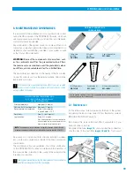
Image 28.
Depending on how old the installation is, there may be no right
angle valve and that it is necessary to turn off the general stop-
cock in the home.
Immediately afterwards, depressurise the installation by turning
on the tap of the sink and wait until water comes out of it.
Make sure that the connection to the appliance is going to be carried
out in the cold water pipe connection. If the connection is made in
the hot water pipe it may damage important components of the system.
(Generally the cold water pipe connection is found to the right).
Unscrew the connection of the hose or the flexible pipe,
image 29
. Have a recipient or cloth ready to collect or wipe
up the water that may come out of the flexible pipe when
you unscrew it. Insert it into the connection in the wall and
the valve or flexible pipe to the 1/2” wall adaptor,
exploded
view No. 8 on flap
.
The flat 1/2” joint that is inserted makes it unnecessary to
use a sealant. (Teflon wire, liquid Teflon, hemp twine, etc.),
image 30
.
Assemble the 1/4” manual in-let valve in overlap in the left hole
of the wall adapter.
Image 31
.
A sealant should be added to this valve to ensure that it has
been assembled correctly and that it is water-tight. The use of
Teflon is recommended, as it is a clean, quick sealant and safe
6. Installation of the system
30
29
exploded view No.8 on flap
on brass threads. The two connectors (1/2” and 1/4”) must
be screwed in with a monkey wrench until you are sure that
it is properly assembled and water-tight. Subsequently, in the
male connector of the 1/2” adapter connect the flexible pipe
(usually female).
Should it be necessary to install a special component, it should not
be iron or contain iron components as on rusting these can
reduce the performance of the appliance.
To ensure the proper installation and water-tightness of the
connections made, open the right angle entry valve (or where
applicable the general stopcock), first making sure that the tap
of the reverse osmosis appliance on the counter-top has been
turned off. Once the stopcock is open, turn on the tap on the
counter-top to bleed the air that may be inside (beware of any
spurts or splashes of water).
Check the 1/4” valve, as depending on how old it is and the
material used in the assembly of the interior installation of
the house, in some cases, it becomes blocked due to the
incrustations there are in the installation and which come
loose once there is water coming through and pressure.
Next, the white 1/4” tube is connected, between the stop-
cock and the connection of the appliance marked “feed wa-
ter/entrada”,
image 32
. Make sure of the correct entry into
the tube and tightening of the corresponding nuts. The 1/4”
feed valve must remain closed until the end of the installation
of the machine.
6.
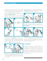
Subsequently, the drain clamp must be assembled,
exploded view No. 12 on flap
. Bear in mind that this clamp is
designed to be assembled on a 40 mm diameter drainpipe
tube. Should this not be the diameter of the drainpipe tube,
contact your components supplier to make the correct
connection.
Using the drill, and this time a 6 mm bit, make a hole be-
tween the mouth of the drainpipe of the sink and the u-bend
(it is recommended that you do it in the upper part of the
tub, so that any rubbish thrown away from the sink does
28
29
CLOSED
31
32
feed water
Summary of Contents for PROLINE PLUS
Page 1: ...INSTRUCTIONS MANUAL PROLINE PLUS PROLINE PLUS PUMP ...
Page 3: ...3 ...
Page 27: ...27 ...


