background image

PureFlow AirDog® 

AirDog® II-5G DF-165 


2011-2016 6.7L Powerstroke 


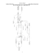
ILLUSTRATION OF COMPONENTS


Summary of Contents for AirDog II-5G

Page 1: ...2016 6 7L Powerstroke PROTECTED BY CANADIAN PATENT US PATENTS AUSTRALIAN PATENT 2 108 391 5 355 860 5 746 184 6 729 310 2005101054 NEW ZEALAND PATENT 532356 Additional Foreign Patents Pending in Europ...

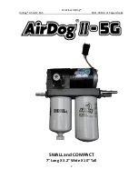
Page 2: ...PureFlow AirDog AirDog II 5G DF 165 2011 2016 6 7L Powerstroke 2 SMALL and COMPACT 7 Long X 3 2 Wide X 10 Tall...

Page 3: ...ication is preset at 65psi from factory for a stock application The regulator is adjustible up to 75 psi for fine tuning the system for performance upgrades WARNING RUNNING THE PUMP ABOVE 75PSI WILL D...

Page 4: ...Quick Connect System The SAE J2044 quick connect system is the most commonly used system in the automotive industry The images below show the formation of SAE J2044 connection To connect the assemblie...

Page 5: ...ets Section 5 Pump Mounting FUEL LINES Section 6 Fuel Line Assembly Section 7A Supply Line to Engine Crew Cab Section 7B Supply Line to Engine Single Cab Section 8 Suction Line from Tank Section 9 Ret...

Page 6: ...INE RETURN LINE to the fuel tank as it was from the factory when the installation is complete If any installation procedure is uncertain contact PUREFLOWAIRDOG for technical assistance SAFETY GUIDELIN...

Page 7: ...5E 2 010 HD 1 Bundle of Plastic Ties 5H 2 1 06 12 1 Spacer 010 3C 0003 A P 1 14ft of Fuel Line HS14 3 1 2 Straight Hose Quick Connect Fitting FQC12S 1 1 2 90 Hose Quick Connect Fitting FQC1290 1 3 8...

Page 8: ...PureFlow AirDog AirDog II 5G DF 165 2011 2016 6 7L Powerstroke 8 ILLUSTRATION OF COMPONENTS...

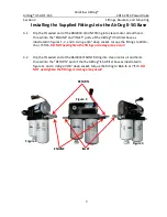
Page 9: ...er base as illustrated in figures 1 2 and 3 Using a 3 4 deep socket torque the fittings to 180in lb or 15ft lb DO NOT overtighten the fittings or damage may occur 4 2 Dip the threaded end of the 06J20...

Page 10: ...should look like figure 6 4 4 Attach the AirDog II 5G to the frame bracket assembly as shown in figure 7 using the supplied hardware in the mounting bracket hardware kit The brackets are universal and...

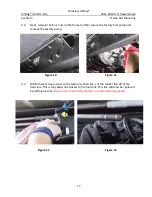
Page 11: ...pump NOTE The supply lines are Yellow and the return lines are Blue 5 2 Remove the factory quick connects by first lifting the lock 1 to the unlock position then by pressing down on the tab 2 while pu...

Page 12: ...e the factory fuel pump and remove the factory pump 5 4 While there is clear access to the factory suction line cut the rubber line off of the hard line This is the yellow line closest to the fuel tan...

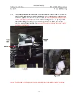
Page 13: ...s Tighten until the lock washers are flat DO NOT OVERTIGHTEN OR DAMAGE TO THE PLATES MAY OCCURE Be sure to tuck the AirDog II 5G as far up as possible without it rubbing on anything to prevent damage...

Page 14: ...it into the fuel line HS14 until all three barbs are covered Figures 17 and 18 The fuel line end should look like Figure 18 6 2 Now plug that fuel line with that fitting into the connection on the ei...

Page 15: ...nstallation between the Single Cab and Quad Cab applications will vary slightly If your application is a single cab continue to section 7B 7A 1 The factory supply line Yellow that was disconnected fro...

Page 16: ...member Refer to Fig 22 You may need to use a fuel line quick disconnect tool Fig 23 This tool can be picked up at any local auto parts store Once removed discard the factory line 7B 2 Now assemble one...

Page 17: ...uel line along the frame as mentioned in step 6 3 to the Engine port in the AirDog Cut the fuel line to length and insert fuel line end FQC12S per step 6 1 Once the fitting is installed connect it to...

Page 18: ...ifferent fittings from one another for the next step Crew Cab trucks will need to use an FQC1290 fitting and the Single Cab trucks will need to use the FQC12S fitting 8 2 For Crew Cab applications ass...

Page 19: ...he fuel line Reference section 6 using fuel line end FCQ38S and plug it into the J2044 male connection on the return Y A click will be heard once the fitting is properly connected 9 3 Run the fuel lin...

Page 20: ...Holder to the Vehicle 10 1 Secure the relay and fuse holder to the vehicle Be sure to rout the wires away from any moving parts The relay is illustrated below in figure 36 The fuse holder mounting is...

Page 21: ...nnected to the battery or the alternator Connecting the power supply leads to the alternator instead of the battery will create a corrosion free connection Black Red 10 3 Route the power supply leads...

Page 22: ...ECKING FOR EXCESSIVE PUMP NOISE NOTE Each AirDog II has been manufactured in a Quality Controlled process and wet tested for operation and performance before shipment This is a smooth running system W...

Page 23: ...xperience excessive water in fuel conditions When installing the water separator be sure to clean the underside of the AirDog base Follow the instructions printed on the pre filter for proper tighteni...

Page 24: ...Gerotor CLEANING DEBRIS CHECKING FOR DAMAGE IN TO THE GEROTOR ASSEMBLY STEP 4 Remove the O rings and clean inspect the inside of the Gerotor pocket STEP 5 Reinstall the center gear STEP 6 Align and in...

Page 25: ...ely PRESSURE ADJUSTMENT FOR THE 6 7L POWERSTROKE Turn the adjuster screw counter clockwise to reduce the output pressure or clockwise to increase the pressure Be sure to re torque the jam nut after ad...

Page 26: ...event shall the SELLER be liable for any special incidental indirect or consequential damages of any kind or nature whether or not the BUYER of the PRODUCT was advised of the possibility of damage or...

Page 27: ...he event the phone call is accidentally disconnected and then transfer the customer to a PureFlow AirDog Customer Service Representative Should a Customer Service Representative not be available the T...

Reviews: