background image

www.pulsar.pl   


INTRE   


4.4  STEP 3 

– The TCP/IP Network settings.


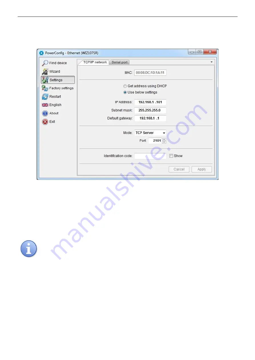
Press the ‘Settings" button from the menu on the left side of the PowerConfig program window. A window 

will be displayed in the right part of the screen. Choose the "Network TCP / IP” from the top tab menu. This window 
allows setting the IP address for Ethernet communication. 


Fig. 7. The TCP/IP Network settings. 


There are two options: 
 
"Get an address using DHCP" - automatic IP address assignment (setting is not recommended); 
After selecting this option, the IP address will be automatically assigned by a router each time the interface module 
is turned on. 
 
„Use the settings below "” – assign a static IP address (

recommended setting

); 

When selecting this option, type the available network address for interface identification.  
In the next fields, enter the port number and subnet mask if required. 


Before setting the network IP address, make sure it is not used by any device on the network. 


The next parameters to be set in the "TCP/IP Network" tab are the "TCP Server" operation mode and the 

port number 

– 2101 by default. 


To increase security, the INTE interface module offers the possibility to assign an identification code to use 

when searching for network modules. If the code is assigned, it then must be entered 

in the „Code” field each time 

the search is performed. 
 
Once the settings are entered, press the 

“Apply”


button”.


Summary of Contents for RS485-ETHERNET

Page 1: ...RS485 ETHERNET Interface v 1 1 CODE INTRE EN Edition 6 from 27 11 2019 Supercedes edition 5 from 25 01 2019 ...

Page 2: ...7 4 3 STEP 2 Interface network search 8 4 4 STEP 3 The TCP IP Network settings 9 4 5 STEP 4 Setting the serial port parameters the Serial tab 10 5 Configuration of power supplies 11 5 1 Configuration of power supplies of the PSBEN series with LCD display 11 5 2 Configuration of power supplies of the PSBEN series with LED display 12 5 3 Configuration of power supplies of the EN54 series with LCD di...

Page 3: ... device used to convert signals between the RS485 bus and the Ethernet network and is designed to operate with power supplies of the PSBEN or EN54 series in the LAN WAN network For proper operation the unit requires an external power supply in the range of 10 30 V DC e g drawn from a PSU of the PSBEN or EN54 series The physical connection of the interface takes place under galvanic isolation The u...

Page 4: ...he components Component No Description 1 Diody LED optical indication PWR supply voltage TX transmitting data RX receiving data 2 RST jumper resetting the interface settings 3 RJ45 ETHERNET interface socket see Table 2 4 RS485 bus connector A B RS485 data transmission SG signal ground 5 Green LED Ethernet connection indication 6 Yellow LED signaling the operating status 7 10 30 V DC power supply c...

Page 5: ...topology is recommended while the star topology should be avoided If the wires are long enough it is recommended to use shielded cables to avoid errors during the communication and to lower the susceptibility to noise and radio interference It is recommended to mount the terminal resistors at the ends of the bus with a resistance close to the impedance of the used cable which is 120 Ohm 3 3 Connec...

Page 6: ...e Ethernet cable through the cable gland and the appropriate hole in the enclosure and then clamp the RJ45 plug Next plug the cable in the RJ45 socket of the interface Plug the other end of the twisted pair in the RJ45 socket of the router usually marked as LAN 4 Lead the power supply cable through the cable duct and the appropriate hole in the enclosure and then connect it to the Power power supp...

Page 7: ...tion of the router in order to establish a connection with the interface When using a switch no configuration is required When using a router ask the administrator about the current configuration of the router or restore the factory settings accordingly to the information included in the further part of this manual 4 2 STEP 1 Restoring the factory settings Router To restore the factory settings of...

Page 8: ... IP Address field If the interface is configured with an identification code then it must be entered in the Code field After selecting the search method press the Search button Fig 5 Window of the PowerConfig program network interface search Once the search process is finished all the NTE interfaces available on the network will be displayed in the program window Identification of the interface th...

Page 9: ...terface module is turned on Use the settings below assign a static IP address recommended setting When selecting this option type the available network address for interface identification In the next fields enter the port number and subnet mask if required Before setting the network IP address make sure it is not used by any device on the network The next parameters to be set in the TCP IP Networ...

Page 10: ...15 200 baud communication speed or other communication parameters are set enter the parameters in the COM port settings window so that they match the parameters set in the power supply The maximum available communication speed supported by a given power supply unit and other communication parameters should be checked in the PSU menu see Chapter 5 Once set press the Apply button Once all the above ...

Page 11: ...enter the setup mode press the SET button from the main screen use the or buttons to display the PSU menu press the SET button use the or buttons to display the Transmission menu The Transmission menu is at the bottom of the screen press the SET button the prompt will appear at the end of the line use the or buttons to set the 115 2k 8E1 if the PSU does not support this speed choose other maximum ...

Page 12: ...be displayed press the right arrow the tSt parameter will be displayed press OK The information about the transmission speed will be displayed use the or buttons in order to set the required transmission speed confirm by pressing OK the trS parameter will be displayed press the right arrow na the trP parameter will be displayed press OK The information about the parity of the transmission will be ...

Page 13: ...ly press the rightmost and leftmost buttons on the LED panel use the or buttons to display the PSU menu press the SET button use the or buttons to display the Transmission menu The Transmission menu is at the bottom of the screen press the SET button the prompt will appear at the end of the line use the or buttons to set the 115 2k 8E1 if the PSU does not support this speed choose other maximum sp...

Page 14: ...layed press the right arrow The trS parameter will be displayed press OK The information about the selected transmission speed will be displayed use the or buttons in order to set the required transmission speed confirm by pressing OK The trS parameter will be displayed again press the right arrow The trP parameter will be displayed press OK The information about the selected parity of the transmi...

Page 15: ...rface Refresh period of the preview ms 100 60 000ms Refresh period of the parameters in the preview window CONNECTION Type Modbus RTU TCP IP connection type depending on the type of interface TCP Address e g 192 168 1 101 PSU Ethernet network address Each Ethernet interface in the network has a unique address TCP port e g 2101 Response time ms 100 60 000ms The response time from the power supply i...

Page 16: ...ditions humidity 10 o C 40 o C relative humidity 20 90 no condensation Dimensions LxWxH 121 x 81 x 60 mm Net gross weight 0 22kg 0 26kg Protection class IP65 Storage temperature 20ºC 60ºC Others Permission of the Scientific and Research Centre for Fire Protection National Research Institute for use with power supplies of the EN54 series in fire alarm systems Pulsar sp j Siedlec 150 32 744 Łapczyca...

Reviews: