background image

www.pulsar.pl   


PSBEN5012C/LCD 


13 

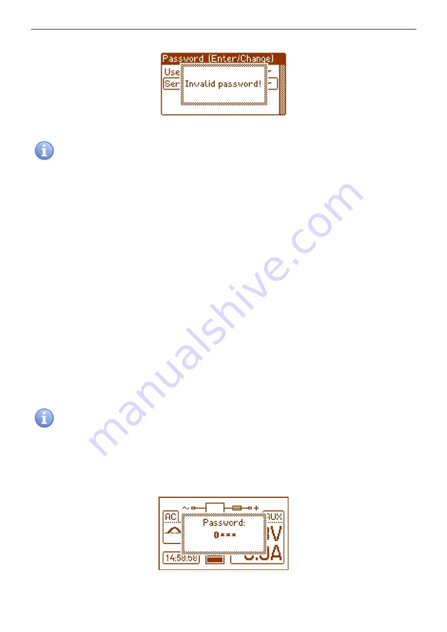
If the typed password is incorrect, the following message will appear: 


Fig. 11. The message after entering a wrong keypad password. 


If  none  of  the  buttons  is  pressed  within  the  next  30  seconds,  the  PSU  settings  will  be  locked 

automatically. 


Password change. 

After entering the correct password, it is a possibility to change it. Choose the password that will be altered 

and enter the new one. 
 
 
Skipping the access password. 

If the password of access to the PSU’s settings is not required, it can be skipped by typing ‘0000’ as a new 

password. 

 
Keypad password 

”0000”

 unlocks the access to the keypad. 

User password 

”0000”

 unlocks the access from the user’s level. 

Installer password 

”0000”

 unlocks the access from the installer’s level. 


Erasing passwords. 

 
If by any chance, the passwords have been lost, there is a procedure that will allow reassigning the 

passwords.  

Please, do as follows: 
a)  unplug the PSU from the AC network and the battery for at least 10 seconds 
b)  press the STOP button on the pcb of the PSU 
c)  plug in the PSU to the AC power and the battery while having the button pressed for another 10 

seconds 

d)  the PSU will display the message: 

”Access unlocked”


e)  confirm by pressing the ‘SET’ button 
f)  go to menu 

”Settings -> Password”

 and change the passwords into new ones 


If  none  of  the  buttons  is  pressed  within  the  next  30  seconds,  the  PSU  settings  will  be  locked 

automatically. 


Keypad password. 
 

If the keypad has been locked due to the access password, the activation of the keypad access will occur 

after minimum 30 seconds of not pressing any buttons on the desktop. After this time, pressing any button on the 
desktop will display a  window  witch  a password  demand. The password  is to be entered using  ‘<’ or ‘>’  as it has 
been explained above. 


Fig. 12. Keypad password demand. 


Summary of Contents for PSBEN 5012C/LCD

Page 1: ...PSBEN 5012C LCD v 1 0 PSBEN 13 8V 5A 17Ah EN LCD Buffer switched mode power supply unit EN Edition 4 from 01 02 2013 Supersedes the 3 from 20 11 2012edition...

Page 2: ...the EPS output lag 16 Setting the communication address 17 3 4 3 Desktop 17 Setting the language of messages 18 Setting the date 18 Setting the time 19 Setting the highlighting 19 Setting the contrast...

Page 3: ...QUIREMENTS 30 7 2 INSTALLATION PROCEDURE 30 8 OPERATION AND USE 31 8 1 OVER VOLTAGE PROTECTION OVP AT THE PSU OUTPUT 31 8 2 OVERLOAD OF THE PSU 31 8 3 SHORT CIRCUIT AT THE PSU OUTPUT 31 8 4 BATTERY RE...

Page 4: ...operation history failure history real time clock battery backed optical indication of PSU overload OVL acoustic indication of failure adjustable times indicating AC power failure technical inputs ou...

Page 5: ...d to the Alarm Receiving Centre ARC in accordance with 9 2 PN EN 50131 1 Output voltage 0 28A 3A battery charge General use if the PSU is not mounted within an installation which is PN EN 50131 compli...

Page 6: ...off Caption jumper on jumper off 6 VADJ potentiometer DC voltage adjustment 7 BUZZER acoustic indicator 8 FBAT fuse in the battery circuit 9 Connectors AC AC power input BAT DC power battery output A...

Page 7: ...N 230V AC power connector PE connector 6 Battery connectors positive BAT red negative BAT black 7 Grip of tamper resistance Fig 3 The view of the PSU 3 Operating status indication 3 1 Control panel T...

Page 8: ...lay The main screen of the LCD display shows basic electrical parameters and informs about the current PSU state Fig 5 The main screen Table 4 Description of the symbols on the main screen Screen fiel...

Page 9: ...tatus during operation Highlighting of an element informs about an active state and reflects the status of LEDs on the pcb of the PSU see table 1 12 Fig 7 Screen parameters of the PSU Table 5 Descript...

Page 10: ...analysis of the values shown on the chart the time range of the chart screen can be adjusted in the bottom axis Here are the available ranges 8h 24h 2days week weekly In order to change the displayed...

Page 11: ...erates 3 levels of access to configuration which limit the possibility of changing the PSU s settings from the level of the LCD desktop They are protected with separate passwords Keypad password locks...

Page 12: ...ear with or choose the right level of the password confirm your choice with the SET button with or enter the first digit confirm your choice with the SET button with or enter the second digit confirm...

Page 13: ...swords have been lost there is a procedure that will allow reassigning the passwords Please do as follows a unplug the PSU from the AC network and the battery for at least 10 seconds b press the STOP...

Page 14: ...to the PSU NO battery not connected to the PSU see chapter 4 6 Battery test YES battery test on NO battery test off see chapter 4 3 Battery protection YES battery protection function disconnection on...

Page 15: ...onfirm your choice with the SET button Setting the battery test with or choose the Battery test menu press the SET button you will see the prompt at the end of the line with or set YES or NO YES batte...

Page 16: ...nction disconnection on NO battery protection function disconnection off confirm your choice with the SET button Setting the EPS output lag with or choose the EPS output lag menu press the SET button...

Page 17: ...mputer confirm your choice with the SET button 3 4 3 Desktop The facility is only available after entering the correct user s or installer s password The Desktop menu enables setting the current date...

Page 18: ...you will see the prompt at the end of the line with or choose the language of messages confirm your choice with the SET button Setting the date with or choose the Date menu press the SET button the pr...

Page 19: ...ection with or set the minutes press the SET button the prompt will move to the second section with or set the seconds approve the settings with the SET button Setting the highlighting Intensity of th...

Page 20: ...t to the constant option with or change the setting into 60 s press the SET button the prompt will move to the end of the line with or set the demanded screen brightness approve your choice with the S...

Page 21: ...y the output is close In case of a power failure the PSU will switch the output into the open state after a period of time determined by the EPS output lag facility see 3 4 2 table 7 APS FLT output in...

Page 22: ...IN technical input has been implemented with galvanic isolation between the PSU s systems and the devices attached Fig 16 Electrical diagram of the EXT IN input The electrical diagram below shows the...

Page 23: ...attery test facility can be switched off Deactivating activating the test enter the PSU settings from the level of the LCD desktop by pressing the SET button Then choose PSU Battery protection YES NO...

Page 24: ...3 7h 2 2 J1 J2 J3 10h12m 1 5 J1 J2 J3 25h30m 0 6 J1 J2 J3 4 6 Operation without a battery In case of an expected PSU operation without an attached battery make a necessary configuration setting from t...

Page 25: ...ces 5 1 Communication in the wi fi wireless network The Wi Fi wireless communication is to be implemented on the basis of additional interfaces WI Fi INTW and RS485 WiFi operating within 2 4GHz freque...

Page 26: ...Ethernet communication with the use of the INTE interface The RS485 ETHERNET INTRE interface is a device intended for converting signals between the RS485 bus and the Ethernet network To work correct...

Page 27: ...ation with the use of the interfaces INTR and INTUR 5 4 USB TTL communication If the PSU does not cooperate with any of previously mentioned network and the access to the parameters adjustment and mem...

Page 28: ...4 4A 0 6A battery charge Io 3 5A 1 5A battery charge Io 2 8A 2 2A battery charge Io 2A 3A battery charge Output voltage setting escalation and keeping time 5ms 40ms 18ms Output voltage adjustment rang...

Page 29: ...x 355 x 100 8 WxHxD mm 2 Fixing 300 x 318 x 6 x4 WxH Fitting battery 17Ah 12V SLA max Net gross weight 6 0 6 4 kg Enclosure Steel plate DC01 1mm colour RAL 9005 black Closing Cheese head screw x2 at...

Page 30: ...and assigning an appropriate fuse in the fuse box The electrical system shall follow valid standards and regulations 7 2 Installation procedure CAUTION Before installation cut off the voltage in the 2...

Page 31: ...peration and use 8 1 Over voltage protection OVP at the PSU output In case of voltage exceeding 15 5V 0 5V at the regulator s output the system cuts off the power at the outputs to protect the battery...

Page 32: ...igh output voltage Output voltage 14 7V F07 ON 2 flashes ON PSU FLT Too high battery voltage Battery voltage 14V F08 ON 3 flashes ON PSU FLT Battery charging circuit failure Too low output voltage of...

Page 33: ...ssibilities to carry out the repairs or if the equipment has been conditionally accepted due to the breaking warranty terms by the claimant 7 All the services rendered by force of the warranty are car...

Reviews: