background image

www.pulsar.pl   


PSBEN5012C/LCD 


10 


PSU technical outputs’ status: 
EPS – AC network presence indication 


open 

= AC power failure 


close   = AC power - O.K. 

PSU – PSU failure indication 


open 

= failure 


close   = PSU working correctly - O.K.  

APS – battery failure indication 


open 

= battery failure 


close 

= battery O.K.  


3.3.3 Screen – history of the PSU’s parameters. 


During normal operation the PSU records the electrical parameters delivered to the AUX output and saves 

them in its non-volatile memory. The saving occurs every 5 minutes and the internal memory can store up to about 
6100  values.  The  memory  works  in  a  circular  cycle.  When  the  memory  becomes  fulfilled,  the  oldest  entries  get 
replaced with the newest ones. 

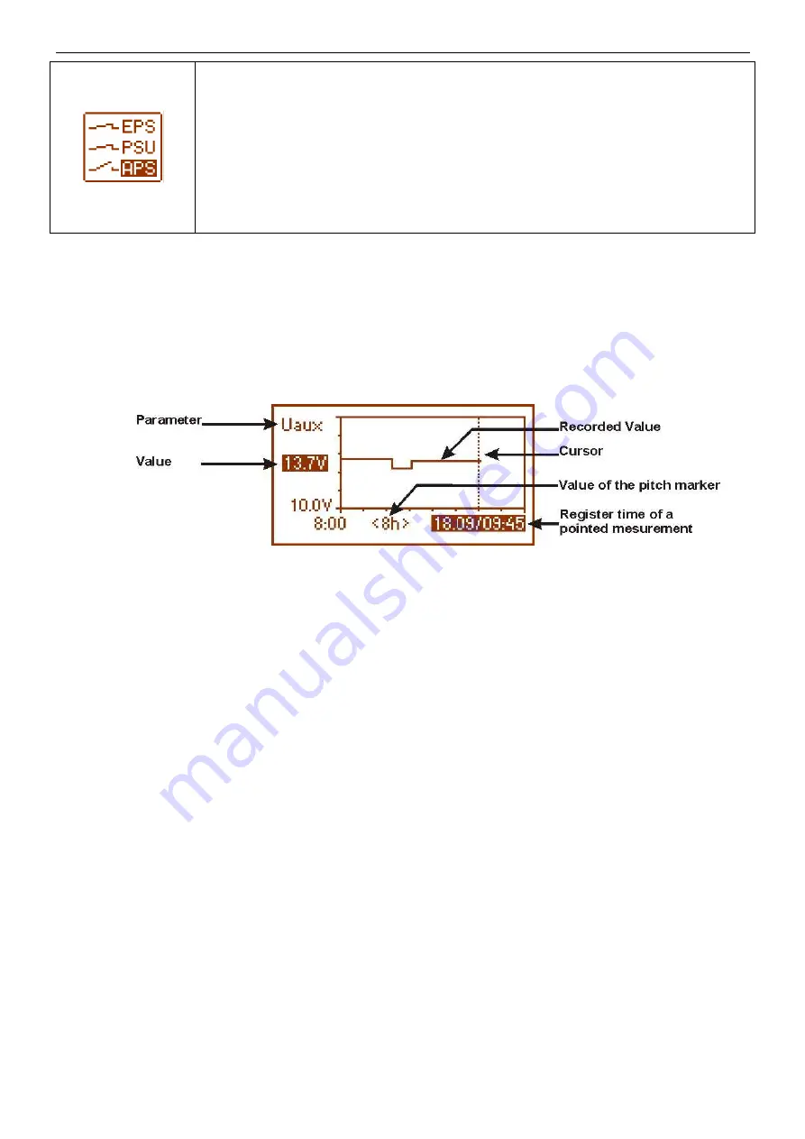
The screen of the parameters history enables reading of the stored parameters and scanning the values on 

a  chart.  The  screen  features  a  time  axis,  located  horizontally  in  the  bottom  part  of  the  chart,  and  the  axis  of  a 
selected parameter – located vertically in the left part. The cursor can be moved into various time points via  ‘<’ and 
‘>’ buttons. For each time point, the corresponding value in can be read.  


      Fig. 8. Screen of the history of PSU’s parameters. 

 
From the given chart entries, the values of the following parameters can be read: 
Uaux   

- output voltage (approximate value within 5 minute period) 

Uaux max 

- maximum output voltage 

Uaux min 

- minimum output voltage 

Iaux   

- output current (approximate value within 5 minute period) 

Iaux max 

- maximum output current 

Iaux min 

- minimum output current 


For optimal reading and analysis of the values shown on the chart, the time range of the chart screen can 

be adjusted in the bottom axis. Here are the available ranges: 
<8h>  
<24h> 
<2days> 
<week>
 (weekly) 

In order to change the displayed parameter, highlight its name by pressing the ‘SET’ button. Then, with the 

‘<’  and  ‘>’  buttons  choose  the  requested  measurement.  Pressing  the  ‘SET”  button  again  will  highlight  the  time 
range  of  the  chart,  which  can  be  changed  with  the  ‘<’  and  ‘>’  buttons.  Another  pressing  of  the  ‘SET’  button  will 
enable  moving  the  cursor  (vertical  dotted  line  on  the  chart)  along  the  time  line  with  the  ’<’  and  ‘>’  buttons.  The 
values of currently chosen parameter and the register time pointed by the cursor will also be highlightened, 
 

3.3.4 Screen – failure history. 
If any incorrect electrical parameters appear during the operation, the PSU will begin indicating the failure 

by cyclical switching on and off the LCD display illumination, illuminating the failure LED on the panel and activating 
the acoustic indication (provided, it has not been switched off). 

The  screen  of  the  PSU  failure  history  enables  overviewing  the  events  recorded  by  the  internal  diagnostic 

system. The memo  can  store  over  2000  events  carrying  information  about  the  fault  type,  time  of  occurrence  and 
values  of  the  voltages  or  load  current.  Additionally,  on  the  basis  of  the  stored  parameters,  the  diagnostic  system 
assigns the fault code characteristic for a particular event. 

The  operation  history  can  be  previewed  by  pressing  ’<’  or  ‘>’.  It  can  be  done  in  two  modes:  short  (date, 

time, code, fault description) or full - with additional information about values of voltages and current, and status of 
inputs and outputs. Switching between the modes is to be done by the ‘SET’ button. 


Summary of Contents for PSBEN 5012C/LCD

Page 1: ...PSBEN 5012C LCD v 1 0 PSBEN 13 8V 5A 17Ah EN LCD Buffer switched mode power supply unit EN Edition 4 from 01 02 2013 Supersedes the 3 from 20 11 2012edition...

Page 2: ...the EPS output lag 16 Setting the communication address 17 3 4 3 Desktop 17 Setting the language of messages 18 Setting the date 18 Setting the time 19 Setting the highlighting 19 Setting the contrast...

Page 3: ...QUIREMENTS 30 7 2 INSTALLATION PROCEDURE 30 8 OPERATION AND USE 31 8 1 OVER VOLTAGE PROTECTION OVP AT THE PSU OUTPUT 31 8 2 OVERLOAD OF THE PSU 31 8 3 SHORT CIRCUIT AT THE PSU OUTPUT 31 8 4 BATTERY RE...

Page 4: ...operation history failure history real time clock battery backed optical indication of PSU overload OVL acoustic indication of failure adjustable times indicating AC power failure technical inputs ou...

Page 5: ...d to the Alarm Receiving Centre ARC in accordance with 9 2 PN EN 50131 1 Output voltage 0 28A 3A battery charge General use if the PSU is not mounted within an installation which is PN EN 50131 compli...

Page 6: ...off Caption jumper on jumper off 6 VADJ potentiometer DC voltage adjustment 7 BUZZER acoustic indicator 8 FBAT fuse in the battery circuit 9 Connectors AC AC power input BAT DC power battery output A...

Page 7: ...N 230V AC power connector PE connector 6 Battery connectors positive BAT red negative BAT black 7 Grip of tamper resistance Fig 3 The view of the PSU 3 Operating status indication 3 1 Control panel T...

Page 8: ...lay The main screen of the LCD display shows basic electrical parameters and informs about the current PSU state Fig 5 The main screen Table 4 Description of the symbols on the main screen Screen fiel...

Page 9: ...tatus during operation Highlighting of an element informs about an active state and reflects the status of LEDs on the pcb of the PSU see table 1 12 Fig 7 Screen parameters of the PSU Table 5 Descript...

Page 10: ...analysis of the values shown on the chart the time range of the chart screen can be adjusted in the bottom axis Here are the available ranges 8h 24h 2days week weekly In order to change the displayed...

Page 11: ...erates 3 levels of access to configuration which limit the possibility of changing the PSU s settings from the level of the LCD desktop They are protected with separate passwords Keypad password locks...

Page 12: ...ear with or choose the right level of the password confirm your choice with the SET button with or enter the first digit confirm your choice with the SET button with or enter the second digit confirm...

Page 13: ...swords have been lost there is a procedure that will allow reassigning the passwords Please do as follows a unplug the PSU from the AC network and the battery for at least 10 seconds b press the STOP...

Page 14: ...to the PSU NO battery not connected to the PSU see chapter 4 6 Battery test YES battery test on NO battery test off see chapter 4 3 Battery protection YES battery protection function disconnection on...

Page 15: ...onfirm your choice with the SET button Setting the battery test with or choose the Battery test menu press the SET button you will see the prompt at the end of the line with or set YES or NO YES batte...

Page 16: ...nction disconnection on NO battery protection function disconnection off confirm your choice with the SET button Setting the EPS output lag with or choose the EPS output lag menu press the SET button...

Page 17: ...mputer confirm your choice with the SET button 3 4 3 Desktop The facility is only available after entering the correct user s or installer s password The Desktop menu enables setting the current date...

Page 18: ...you will see the prompt at the end of the line with or choose the language of messages confirm your choice with the SET button Setting the date with or choose the Date menu press the SET button the pr...

Page 19: ...ection with or set the minutes press the SET button the prompt will move to the second section with or set the seconds approve the settings with the SET button Setting the highlighting Intensity of th...

Page 20: ...t to the constant option with or change the setting into 60 s press the SET button the prompt will move to the end of the line with or set the demanded screen brightness approve your choice with the S...

Page 21: ...y the output is close In case of a power failure the PSU will switch the output into the open state after a period of time determined by the EPS output lag facility see 3 4 2 table 7 APS FLT output in...

Page 22: ...IN technical input has been implemented with galvanic isolation between the PSU s systems and the devices attached Fig 16 Electrical diagram of the EXT IN input The electrical diagram below shows the...

Page 23: ...attery test facility can be switched off Deactivating activating the test enter the PSU settings from the level of the LCD desktop by pressing the SET button Then choose PSU Battery protection YES NO...

Page 24: ...3 7h 2 2 J1 J2 J3 10h12m 1 5 J1 J2 J3 25h30m 0 6 J1 J2 J3 4 6 Operation without a battery In case of an expected PSU operation without an attached battery make a necessary configuration setting from t...

Page 25: ...ces 5 1 Communication in the wi fi wireless network The Wi Fi wireless communication is to be implemented on the basis of additional interfaces WI Fi INTW and RS485 WiFi operating within 2 4GHz freque...

Page 26: ...Ethernet communication with the use of the INTE interface The RS485 ETHERNET INTRE interface is a device intended for converting signals between the RS485 bus and the Ethernet network To work correct...

Page 27: ...ation with the use of the interfaces INTR and INTUR 5 4 USB TTL communication If the PSU does not cooperate with any of previously mentioned network and the access to the parameters adjustment and mem...

Page 28: ...4 4A 0 6A battery charge Io 3 5A 1 5A battery charge Io 2 8A 2 2A battery charge Io 2A 3A battery charge Output voltage setting escalation and keeping time 5ms 40ms 18ms Output voltage adjustment rang...

Page 29: ...x 355 x 100 8 WxHxD mm 2 Fixing 300 x 318 x 6 x4 WxH Fitting battery 17Ah 12V SLA max Net gross weight 6 0 6 4 kg Enclosure Steel plate DC01 1mm colour RAL 9005 black Closing Cheese head screw x2 at...

Page 30: ...and assigning an appropriate fuse in the fuse box The electrical system shall follow valid standards and regulations 7 2 Installation procedure CAUTION Before installation cut off the voltage in the 2...

Page 31: ...peration and use 8 1 Over voltage protection OVP at the PSU output In case of voltage exceeding 15 5V 0 5V at the regulator s output the system cuts off the power at the outputs to protect the battery...

Page 32: ...igh output voltage Output voltage 14 7V F07 ON 2 flashes ON PSU FLT Too high battery voltage Battery voltage 14V F08 ON 3 flashes ON PSU FLT Battery charging circuit failure Too low output voltage of...

Page 33: ...ssibilities to carry out the repairs or if the equipment has been conditionally accepted due to the breaking warranty terms by the claimant 7 All the services rendered by force of the warranty are car...

Reviews: