Pulsar ADOC552415 Quick Start Manual Download Page 5

ww.pulsar.pl 


ADOC552415 


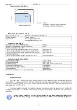
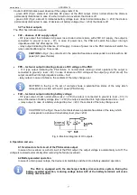
Temperature characteristics. 


Chart 1.  
Acceptable output current from the PSU 
depending on ambient temperature. 


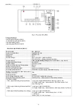
Mechanical specifications (tab. 3). 

Enclosure dimensions 

159 x 97 x 38+23 [mm] (LxWxH)(+/- 2) 

Net/gross weight 

0,57kg / 0,61kg 

Connectors 

power supply Φ0,64÷1,63 
technical outputs: Φ0,41÷1,63 

Operation safety (tab.4). 

Protection class PN-EN 60950-1:2007 

I (first) 

Degree of Protection PN-EN 60529: 2002 (U) 

IP20 

Electrical strength of insulation: 
- between PSU input circuit and output circuits (I/P-O/P) 
- between input circuit and PE protection circuit (I/P-FG) 
- between output circuit and PE protection circuit (O/P-FG) 

 
3000 V/AC min. 
1500 V/AC min. 
500  V/AC min. 

Insulation resistance: 
- between input circuit and output or protection circuit 

 
100 MΩ, 500V/DC  

Operating specifications (tab.5). 

Operating temperature 

-10ºC...+60ºC  

Storage temperature 

-20ºC...+85ºC 

Relative humidity 

20%...90%, without condensation 

Vibrations during operation 

unacceptable 

Impulse waves during operation 

unacceptable 

Direct insolation 

unacceptable 

Vibrations and impulse waves during transport 

PN-83/T-42106 


2. Installation. 
 

2.1 Requirements 
 

The buffer PSU is to be mounted by a qualified installer, holding relevant permits and licenses (applicable 

and  required  for  a  given  country)  for  230V/AC  interference  and  low-voltage  installations.  The  unit  should  be 
mounted  in  confined  spaces,  with  normal  relative  humidity  (RH=90%  maximum,  without  condensation)  and 
temperature from -10°C to +60°C. 

 
The  device  shall  be mounted  in  a metallic  enclosure  (a  cabinet,  an  intended  case).  In  order  to  fulfil  LVD 

and  EMC  requirements,  the  rules  for:  power-supply,  encasing  and  screening  shall  be  followed,  according  to 
application.  


During  normal  operation,  the  total  current  drawn  by  the  device  may  not  exceed  I=1,5A. 
Maximum battery charging current: 0,16A. Total current of the rec battery: 1,66A max. 


Summary of Contents for ADOC552415

Page 1: ...ADOC552415 v 1 0 ADOC 27 6V 1 5A OC Enclosed buffer switch mode power supply unit with automatic operation control EN Edition 1 from 29 10 2013 Supercedes edition ...

Page 2: ...NTENTS 1 Technical description 1 1 General description 1 2 Block diagram 1 3 Description of PSU components and connectors 1 4 Specifications 2 Installation 2 1 Requirements 2 2 Installation procedure 3 Operating status indication 3 1 LED indication of operating status 3 2 Technical outputs 4 Operation and use 4 1 Overload or short circuit of the PSU output 4 2 Battery assisted operation 4 3 Mainte...

Page 3: ...voltage 4 FAC AC absence technical output relay type 5 FPS output indicating DC absence PSU failure relay type 6 FLB output indicating battery low voltage relay type 7 FAC AC absence technical output OC type 8 FPS output indicating DC absence PSU failure OC type 9 FLB output indicating battery low voltage OC type 10 B B battery connector 11 V COM DC supply output 12 L N 230V AC power connector PE ...

Page 4: ...t circuit protection SCP electronic automatic recovery Overload protection OLP 105 150 of power supply automatic recovery Battery circuit protection SCP and reverse polarity connection fuse Surge protection varistors Over voltage protection OVP 31 74 37 26V automatic recovery Deep discharge protection UVP U 20V 5 disconnection of the battery terminal Technical outputs FAC output indicating AC powe...

Page 5: ...60ºC Storage temperature 20ºC 85ºC Relative humidity 20 90 without condensation Vibrations during operation unacceptable Impulse waves during operation unacceptable Direct insolation unacceptable Vibrations and impulse waves during transport PN 83 T 42106 2 Installation 2 1 Requirements The buffer PSU is to be mounted by a qualified installer holding relevant permits and licenses applicable and re...

Page 6: ... protection circuit is UNACCEPTABLE It can cause a device failure or an electric shock 4 Connect load loads to proper output connectors of the power supply positive pole is marked as V negative pole as COM 5 Connect the technical outputs to the central or other device 6 Connect the battery to proper output connectors of the power supply positive pole is marked as B negative pole as B 7 Once the te...

Page 7: ...n case of absence of DC voltage at the output e g short circuit the output is switched into high impedance state hi Z relay output In case of a failure the contacts of the relay change over CAUTION In the Fig 2 the set of contacts shows a potential free status of the relay which corresponds to a state with no DC power PSU failure FLB technical output indicating battery voltage OC type output Under...

Page 8: ...vide warranty repairs at the earliest convenienve however not later that within 14 days from the delivery to the service centre of the manufacturer 6 The repair period mentioned in item 5 may be prolonged if there are no technical possibilities to carry out the repairs or if the equipment has been conditionally accepted due to the breaking warranty terms by the claimant 7 All the services rendered...

Reviews: