

ww.pulsar.pl
ADOC552415
3
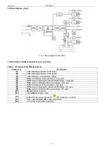
1.2 Block diagram. (fig.1).
Fig.1. Block diagram of the PSU.
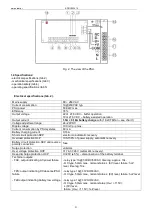
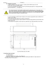
1.3 Description of PSU components and connectors.
Table 1. Elements of the PSU (see fig. 2).
Element no.
Description
[1]
LED indicating presence of AC power
[2]
LED indicating presence of DC power
[3]
LED indicating correct battery voltage
[4]
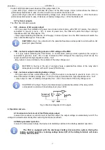
FAC-
AC absence technical output – relay type
[5]
FPS-
output indicating DC absence/PSU failure – relay type
[6]
FLB-
output indicating battery low voltage – relay type
[7]
FAC-
AC absence technical output – OC type
[8]
FPS-
output indicating DC absence/PSU failure - OC type
[9]
FLB-
output indicating battery low voltage - OC type
[10]
B+, B-
battery connector
[11]
+V ,COM
DC supply output
[12]
L-N
230V/AC power connector,
PE protection connector
[13]
V
ADJ
- potentiometer,
DC
voltage adjustment
[14]
Connector of extra LED indication