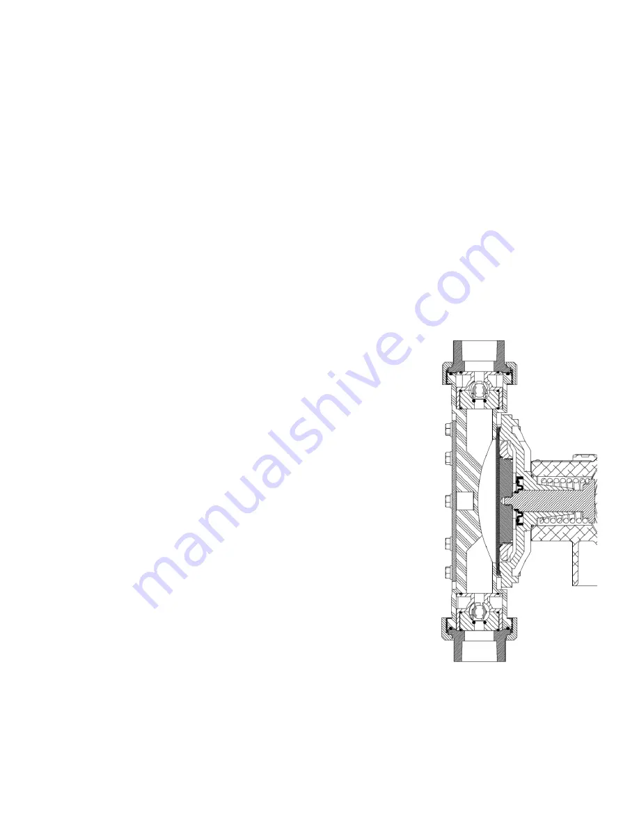
4.2.1 Diaphragm Removal & Reinstallation
1. Adjust the stroke setting to 50% and disconnect the power source to the drive motor.
2. Relieve all pressure from the piping system.
3. Close the inlet and outlet shutoff valves.
4. Place a pan underneath the pump head adaptor to catch any liquid leakage.
5. Disconnect piping to the reagent head and drain any process liquid, following all recommended
material safety precautions.
6. Remove all but one top reagent head bolt. Product will leak out between the pump head adaptor
and reagent head as the bolts are loosened. Use prescribed engineering controls to prevent
exposure and accidental discharge to environment.
7. Tilt the head and pour out any liquids retained by the check valves into a suitable container,
continuing to follow safety precautions as appropriate.
8. Remove the final bolt and rinse or clean the reagent head with an appropriate material.
9. Remove the diaphragm by turning it counter-clockwise.
10. Inspect the diaphragm. The diaphragm must be replaced if it is cracked, separated, or obviously
damaged.
11. Install the diaphragm.
12. Ensure that the critical sealing areas of diaphragm, reagent
head, and pump head are clean and free of debris.
13. Thread the diaphragm (clockwise) fully onto the shaft.
14. Install the reagent head bolts and tighten in an alternating
pattern to ensure an even seating force. Torque bolts to
70 in-lb
15. Re-prime the pump following the procedure outlined in
Section 3.3
Figure 12: Reagent Head Assembly Cross Section
10
Summary of Contents for GLM1
Page 4: ......
Page 23: ...8 Dimensional Drawing Dimension table in mm inches 19...


