background image


WIL-10050-E-02


Wilden

®


18 

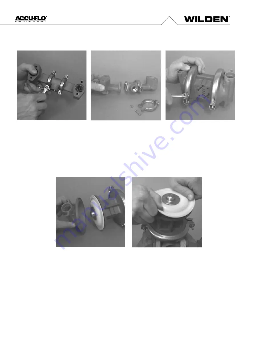
Disassembly / Reassembly


Step 7


Normally the inlet and discharge manifold 

should not be disassembled during regular 
pump maintenance. Should this be necessary 

completely remove and disassemble manifold 
clamp bands. 

Step 8 


Inspect o-rings for wear or damage and 
replace if necessary

Step 9


Use a 7/16" wrench to remove one set  
of clamp bands that secure one liquid 
chamber to the one-piece center section


Step 10


Lift the liquid chamber away from the  
center section to expose the diaphragm  
and outer piston. 

Step 11  


Using an adjustable wrench, or by rotating  
the diaphragm by hand, remove the diaphragm  
assembly from the center section. 


Summary of Contents for WILDEN A1 Accu-Flo

Page 1: ...EOM ENGINEERING OPERATION MAINTENANCE A1 Accu Flo Clamped Metal Pump WIL 10050 E 02 Where InnovationFlows ...

Page 2: ...ction 10 A1T Metal PTFE Fitted T series Center Section 10 A1P Metal Rubber Fitted P series Center Section 11 A1P Metal PTFE Fitted P series Center Section 11 70 30 Operating Conditions 11 A1T Metal Rubber Fitted T series Center Section 12 A1T Metal PTFE Fitted T series Center Section 12 A1P Metal Rubber Fitted P series Center Section 12 A1P Metal PTFE Fitted P series Center Section 12 Section 6 Su...

Page 3: ...lifornia LLC Wil Flex is a trademark of PSG California LLC Saniflex is a trademark of PSG California LLC All trademarks names logos and service marks collectively trademarks in this document are registered and unregistered trademarks of their respective owners Nothing contained in this document should be construed as granting any license or right to use any trademark without the prior written perm...

Page 4: ...scharge of static electricity is a hazard NOTE When installing PTFE diaphragms it is important to tighten outer pistons simultaneously turning in opposite directions to ensure tight fit CAUTION Before any maintenance or repair is attempted the compressed air line to the pump should be disconnected and all air pressure allowed to bleed from pump Disconnect all intake discharge and air lines Drain t...

Page 5: ...Accu Flo 24V AC 12V DC coil PFA coated hardware 0181 Accu Flo 24V AC 12V DC x proof coil PFA coated hardware 0183 Accu Flo 24V AC 12 V DC x proof coil Wil Gard II 110V 0184 Accu Flo 24V DC coil PFA coated hardware 0185 Accu Flo 24V DC x proof coil PFA coated hardware 0512 Adapter block no muffler Pro Flo center Section 0514 Adapter block no muffler standard center section 0516 Adapter block no muf...

Page 6: ...ee shaded area FIGURE 2 When the solenoid valve is deenergized the air valve redirects pressurized air to the back side of diaphragm B The pressurized air forces diaphragm B away from the center section while pulling diaphragm A to the center section Diaphragm B is now on its discharge stroke Diaphragm B forces the inlet valve ball onto its seat due to the hydraulic forces developed in the liquid ...

Page 7: ...40 5 5 J 112 4 4 K 84 3 3 L 102 4 0 M 30 1 2 N 30 1 2 P 8 0 3 R 226 8 9 S 163 6 4 T 81 3 2 U 46 1 8 A1B Metal T Series Center Section DIMENSIONS ITEM METRIC mm STANDARD inch A 28 1 1 B 104 4 1 C 127 5 0 D 198 7 8 E 203 8 0 F 208 8 2 G 224 8 8 H 56 2 2 J 175 6 9 K 140 5 5 L 112 4 4 M 84 3 3 N 102 4 0 P 30 1 2 R 30 1 2 S 8 0 3 DIMENSIONAL DRAWING Section 4 ...

Page 8: ...9 3 5 K 191 7 5 L 102 4 0 M 142 5 6 N 56 2 2 P 226 8 9 R 140 5 5 S 112 4 4 T 84 3 3 U 102 4 0 V 30 1 2 W 30 1 2 X 8 0 3 A1B Metal P Series Center Section DIMENSIONS ITEM METRIC mm STANDARD inch A 28 1 1 B 117 4 6 C 137 5 4 D 198 7 8 E 203 8 0 F 208 8 2 G 224 8 8 H 64 2 5 J 175 6 9 K 140 5 5 L 112 4 4 M 84 3 3 N 102 4 0 P 8 0 3 R 30 1 2 S 30 1 2 DIMENSIONAL DRAWING ...

Page 9: ... 175 6 9 J 140 5 5 K 112 4 4 L 84 3 3 M 102 4 0 N 8 0 3 P 226 8 9 R 163 6 4 S 81 3 2 T 46 1 8 A1P Metal SanifloFDA Accu Flo DIMENSIONS ITEM METRIC mm STANDARD inch A 203 8 0 B 48 1 9 C 102 4 0 D 175 6 9 E 114 4 5 F 46 1 8 G 81 3 2 H 254 10 0 J 226 8 9 K 163 6 4 L 102 4 0 M 142 5 6 N 56 2 2 P 226 8 9 R 102 4 0 S 84 3 3 T 112 4 4 U 140 5 5 V 8 0 3 DIMENSIONAL DRAWING ...

Page 10: ... pumps should be specified so that daily operation parameters will fall in the center of the pump performance curve A1T METAL PTFE FITTED Height 224 mm 8 8 Width 208 mm 8 2 Depth 175 mm 6 9 Est ShipWeight Aluminum 6 kg 13 lbs Stainless Steel 9 kg 20 lbs Alloy C 10 kg 22 lbs Air Inlet 6 mm 1 4 Inlet 13 mm 1 2 Outlet 13 mm 1 2 Suction Lift 3 5 m Dry 11 3 9 3 m Wet 30 6 Disp Per Stroke1 0 05 l 014 ga...

Page 11: ...mance pumps should be specified so that daily operation parameters will fall in the center of the pump performance curve A1P METAL PTFE FITTED Height 241 mm 9 5 Width 208 mm 8 2 Depth 226 mm 8 9 Est ShipWeight Aluminum 6 kg 13 lbs Stainless Steel 9 kg 20 lbs Alloy C 10 kg 22 lbs Air Inlet 6 mm 1 4 Inlet 13 mm 1 2 Outlet 13 mm 1 2 Suction Lift 5 7 m Dry 18 7 9 2 m Wet 30 1 Disp Per Stroke1 0 09 l 0...

Page 12: ...ressure condition This curve can be applied to different pressure conditions to estimate the change in flow due to stroke rate A1P METAL ACCU FLO These curves demonstrate the flow created when the stroke rate is modified under static air and fluid pressure condition This curve can be applied to different pressure conditions to estimate the change in flow due to stroke rate ...

Page 13: ... line large enough to supply the volume of air necessary to achieve the desired pumping rate Consult manual for performance information The use of an air filter before the pump will ensure that the majority of pipeline contaminants will be eliminated For best results the pump should use an air filter regulator system Sound levels are reduced below OSHA specifications using the standard Wilden muff...

Page 14: ...eration with either 12V DC or 24V AC at 60 Hz and the third coil option allows for 110V AC operation ELECTRICAL CONNECTIONS Plumbing Connections Operation A red button on the side of the air valve is a manual override when actuated it will shift the valve as if an electric current had actuated the solenoid RECORDS When service is required a record should be made of all necessary repairs and replac...

Page 15: ...e material being pumped 4 Check for sticking ball check valves If the material being pumped is not compatible with the pump elastomers swelling may occur Replace ball check valves and O ring with the proper elastomers 5 Check to make sure that all suction connections are air tight and that the clamp bands are properly tightened Pump air passages blocked with ice Check for excessive moisture in com...

Page 16: ... Wilden model A1 has a 13 mm 1 2 inlet and outlet The single piece center section consisting of center block and air chambers is molded of nylon polypropylene or acetal All fasteners and hardware are stainless steel All o rings used in the pump are of a special material and shore hardness which should only be replaced with factory supplied parts PLEASE read all directions before starting disassemb...

Page 17: ...the top manifold and lift the center section off the inlet manifold Step 5 Remove the discharge valve balls seats and o rings from the discharge manifold and inspect for nicks gouges chemical attack or abrasive wear Replace worn parts with genuine Wilden parts for reliable performance Step 6 Remove and inspect the seat seat o ring and valve ball from the bottom of the liquid chamber Check for nick...

Page 18: ...lamp bands Step 8 Inspect o rings for wear or damage and replace if necessary Step 9 Use a 7 16 wrench to remove one set of clamp bands that secure one liquid chamber to the one piece center section Step 10 Lift the liquid chamber away from the center section to expose the diaphragm and outer piston Step 11 Using an adjustable wrench or by rotating the diaphragm by hand remove the diaphragm assemb...

Page 19: ...c spring separate from the shaft which remains connected to the opposite side diaphragm assembly Figure 12B PTFE fitted pumps come standard with back up diaphragms NOTE Disc spring not shown on Figure 12B Step 13 To remove the diaphragm assembly from the shaft secure shaft with soft jaws a vise fitted with plywood or other suitable material to ensure shaft is not nicked scratched or gouged Using a...

Page 20: ... side of the intake discharge manifold to ensure a proper sealing surface This is most easily accomplished by placing them on a flat surface prior to tightening their clamp bands to the desired torque see this page for torque specs Be sure to tighten outer pistons simultaneously on PTFE fitted pumps to ensure proper torque values Ensure proper mating of liquid chambers to manifolds prior to tighte...

Page 21: ...WIL 10050 E 02 Wilden 21 EXPLODED VIEW AND PARTS LISTING A1T METAL EXPLODED VIEW Section 8 ...

Page 22: ...55 01 1300 55 01 1300 55 01 1300 55 25 Valve Ball 4 01 1080 55 01 1080 55 01 1080 55 01 1080 56 01 1080 55 26 Valve Seat 4 01 1120 01 01 1120 03 01 1120 04 01 1120 01 01 1120 03 01 1120 04 01 1120 03 01 1120 03 27 Valve Seat O Ring 4 01 1200 55 01 1200 55 01 1200 55 01 1200 56 01 1200 55 28 Diaphragm 2 01 1010 55 01 1010 55 01 1010 55 01 1010 56 01 1010 55 29 Back up Diaphragm 2 N R N R N R 01 106...

Page 23: ...WIL 10050 E 02 Wilden 23 A1P METAL EXPLODED VIEW EXPLODED VIEW AND PARTS LISTING ...

Page 24: ...5160 03 01 5160 04 01 5160 03 01 5160 03 24 Inlet Manifold Elbow 2 01 5220 01 01 5220 03 01 5220 04 01 5220 01 01 5220 03 01 5220 04 01 5220 03 01 5220 03 25 Discharge Manifold Elbow 2 01 5230 01 01 5230 03 01 5230 04 01 5230 01 01 5230 03 01 5230 04 01 5230 03 01 5230 03 26 Screw SHCS ChamberBolt 4 01 6080 03 01 6080 03 01 6080 03 01 6080 03 01 6080 03 01 6080 03 01 6080 03 01 6080 03 27 Vertical...

Page 25: ... A Alloy C N A N A 01 1120 04 N A N A Use in conjunction with seat spacer P N 01 1120 21 500 Electrical Information NEMA 4 UL CSA Part Number Voltage 10 Power W 10 Current A Resistivity Ω DC AC DC AC 60 Hz 50 Hz Inrush Holding 00 2110 99 150 24 48 44 4 8 20 20 20 121 00 2110 99 151 12 24 22 4 8 40 40 40 32 00 2110 99 155 60 120 110 4 8 08 08 06 840 NEMA 7 UL CSA Part Number Voltage 10 Power W 10 C...

Page 26: ...WIL 10050 E 02 Wilden Notes ...

Page 27: ...WIL 10050 E 02 Wilden Notes ...

Page 28: ...d Terrace CA 92313 5651 USA P 1 909 422 1730 F 1 909 783 3440 psgdover com Where Innovation Flows PSG reserves the right to modifythe information and illustrations contained in this document without prior notice This is a non contractual document 05 2018 ...

Reviews: