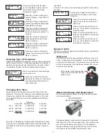
Wiring the Discharge Air Temperature Sensor
Connect the red and white thermostat wires to the LAT Sensor
(TS2) terminals as shown below.
Outdoor Sensor
Red
White
Zoning Panel
LAT
LAT
Leaving Air Temperature Sensor Input
Leaving Air Temperature Sensor Input
From Discharge
Temperature
Sensor (TS2)
Terminal Function
1
2
3
7
To Zoning Panel
Plenum
4
5
6
GND
PRS
OAT
LAT
OAT
LAT
+VDC
SENSOR
S
Zoning Panel
6
GND
PRS
OAT
LAT
OAT
LAT
+VDC
SENSOR
S
Installing the Outdoor Temperature Sensor
Wiring the Outdoor Temperature Sensor
The outdoor temperature sensor (TS3) should be placed in a
shaded location and protected from rain or snow such as under
the eves of a home. Select a location and drill a 5/16-inch
diameter hole to pass the sensor wires through.
Remove screw (1) and separate the base (5) and the cover (2).
Pass a 2-wire thermostat cable through the wall, through the
gasket (6) and through the base (5). Secure the base (5) to the
wall with the gasket (6) between the base and wall using the
two mounting screws (4). Connect the red and white
thermostat wires to the thermistor wires (no polarity) using the
wirenuts (3). Push the wirenuts and wire into the cover and
secure the cover with the screw (1).
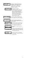
Connect the red and white thermostat wires to the OAS Sensor
(TS3) terminals as shown below.
Zoning Panel
Outdoor Sensor
Red
White
Zoning Panel
OAT
OAT
Outdoor Temperature Sensor Input
Outdoor Temperature Sensor Input
From Outdoor
Temperature
Sensor (TS3)
Terminal Function
Discharge Air Temperature Sensor (Model TS2)
The optional discharge or leaving air temperature sensor (TS2)
can be used to limit discharge air temperature in heating and
cooling to prevent over-heating the plenum or freezing the
indoor coil when only a small number of zones are calling.
o
The panel is factory set for 160 F heating limit for gas heating
o
and 140 F for compressor heating. If the discharge
temperature exceeds these limits, the panel will down-stage or
turn the heating off (fan continues to operate) until the
temperature is within limits. In cooling the factory limit is set to
o
45 F. The PDMi3 can be used to digitally adjust these limits.
Installing the Discharge Air Temperature Sensor
Warning!
Drill a 3/8-inch diameter hole in the plenum or supply duct.
Remove the screw (1) to separate the cover (2) and base (5).
Insert the sensor tube (7) through the gasket and the drilled
hole. Attach the base to the plenum or duct using the two
mounting screws (4). Use the wire nuts (3) to connect the red
and white thermostat wires to the two thermistor wires. Place
the wires into the cover and through the U-shaped tab at the
bottom of the base. Install the cover using the screw (1).
The discharge temperature sensor (TS2) has a 6-inch long,
stainless steel tube that goes into the discharge airstream in
the plenum or main supply duct.
Be careful when drilling holes in the plenum to avoid
puncturing the indoor coil or damaging other components.


