background image

NAS System


User’s Manual 

19 


3.3   Installing Hard Drives 


This section describes the physical locations of the hard drives supported by the 
subsystem and gives instructions on installing a hard drive. The subsystem supports 
hot-swapping allowing you to install or replace a hard drive while the subsystem is 
running. 
 

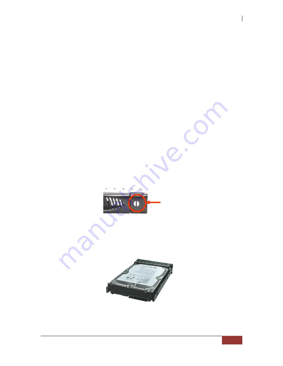
Each Drive Carrier has a locking mechanism. When the Lock Groove, which is located in 
carrier open button, is horizontal, the Drive Carrier is locked. When the Lock Groove is 
vertical, the Drive Carrier is unlocked. Lock and unlock the Drive Carriers by using a flat-
head screw driver.  


3.3.1  Installing 3.5” Disk in a Disk Tray 

a.


Make  sure  the  lock  indicator  is  in  unlocked  position.  To  pull  out  a  disk  tray, 
press the tray open button. 


b.


Pull  out  an  empty  disk  tray.  Pull  the  lever  handle  outwards  to  remove  the 
carrier from the enclosure. 

 
c.


Place the hard drive in the disk tray. 


Tray      

Open  

Button 

Summary of Contents for EN-3160A6-PDC

Page 1: ...NAS System User s Manual Revision 1 0...

Page 2: ...e plugging in any power cords cables and connectors make sure that the power switches are turned off Disconnect first any power connection if the power supply module is being removed from the enclosur...

Page 3: ...Rebuild 11 Chapter 2 Getting Started 12 2 1 Packaging Shipment and Delivery 12 2 2 Unpacking the NAS System 12 2 3 Identifying Parts of the NAS System 13 2 3 1 Front View 13 2 3 1 1 Disk Trays 14 2 3...

Page 4: ...2 5 3 5 hot swappable 6Gb s SATA hard drives Supports RAID levels 0 1 5 6 10 50 Support Smart functional LCD panel Support drive hot spare and automatic hot rebuild Centralization of Data and Storage...

Page 5: ...ring unit Two 2 460W high efficiency hot swap power supplies with PFC RAID Controller Highpoint RocketRAID 2720 Support RAID level RAID 0 1 5 6 10 50 Support drive hot spare and automatic hot rebuild...

Page 6: ...e as several megabytes These stripes are then interleaved in a rotating sequence so that the combined space is composed alternately of stripes from each drive The specific type of operating environmen...

Page 7: ...disk drives that store duplicate data but appear to the computer as a single drive Although striping is not used within a single mirrored drive pair multiple RAID 1 arrays can be striped together to c...

Page 8: ...s a balance between the increased data availability inherent in RAID 1 and RAID 5 and the increased read performance inherent in disk striping RAID 0 These arrays are sometimes referred to as RAID 0 1...

Page 9: ...lower than with RAID 1 Rebuild operations also require more time than with RAID 1 because parity information is also reconstructed At least three drives are required for RAID 5 arrays RAID 6 is essent...

Page 10: ...l physical drives Parity protection is used for data redundancy 3 6 Data is striped across several physical drives Parity protection is used for data redundancy Requires N 2 drives to implement becaus...

Page 11: ...TANT The hot spare must have at least the same or bigger capacity than the drive it replaces 1 4 2 Hot Swap Disk Drive Support The RAID subsystem has built in protection circuit to support the replace...

Page 12: ...ge to the shipping carton may indicate that the contents of the carton are damaged If any damage is found do not remove the components contact the dealer where you purchased the subsystem for further...

Page 13: ...NAS System User s Manual 13 2 3 Identifying Parts of the NAS System The illustrations below identify the various parts of the subsystem 2 3 1 Front View...

Page 14: ...f hard drive is defective or failed the LED is Red LED is off when there is no hard drive Lock Indicator Every Disk Tray is lockable and is fitted with a lock indicator to indicate whether or not the...

Page 15: ...d configure the system See the LCD menu diagram in the next section Parts Function Exit button EXIT Press this button to return to the previous menu Select button This is used to enter the option you...

Page 16: ...ALARM SETTING YES NO CPU NORMAL FAN NORMAL DISK NORMAL POWER NORMAL TEMP NORMAL RAID NORMAL DISK INFORMATION DISK_1 O TEMP 35C DISK_16 O TEMP 35C RAID ARRAY NAME SIZE xxxxGB INFORMATION RAID LEVEL NOR...

Page 17: ...connect a PS 2 mouse or keyboard 8 USB 3 0 Port Four USB 3 0 ports are located at the rear of the system The USB 3 0 port supports the USB 3 0 specification and is compatible to the USB 2 0 1 1 speci...

Page 18: ...hernet port if needed 3 2 Powering On 1 Plug in the 2 power cords into the AC Power Input Socket located at the rear of the NAS system NOTE The NAS system is equipped with redundant full range power s...

Page 19: ...hanism When the Lock Groove which is located in carrier open button is horizontal the Drive Carrier is locked When the Lock Groove is vertical the Drive Carrier is unlocked Lock and unlock the Drive C...

Page 20: ...Close the lever handle until you hear the latch click into place 3 3 2 Installing 2 5 Disk in a Disk Tray a Make sure the lock indicator is in unlocked position To pull out a disk tray press the tray...

Page 21: ...ce the 2 5 hard drive in the disk tray d Install the mounting screws on the bottom part to secure the drive in the disk tray e Slide the tray into a slot f Close the lever handle until you hear the la...

Reviews: