/ŶƐƚĂůůĂƚŝŽŶ͕KƉĞƌĂƚŝŽŶĂŶĚDĂŝŶƚĞŶĂŶĐĞ DĂŶƵĂů
d>͘ϯϭ͘ϮϭϬͲ/KD͘E
^ĞĐƚŝŽŶϰ͗/ŶƐƚĂůůĂƚŝŽŶ
:ƵůϮϬϭϲ
/ŶƐƚĂůůĂƚŝŽŶ
ϭϯ
ϰ͘ϱ
Actuator to Valve Installation
Actuator must be isolated pneumatically and electrically before any (dis)assembly starts.
Stay away from moving parts to prevent serious injuries. When test cycling the actuator
and valve assembly by applying pressure to the A or B port, be aware that there are
moving parts like pinion top, actuator to valve coupling and the valve- blade, ball, plug,
etc.
The actuator is designed to be installed, commissioned and maintained using generic
tools like wrenches, Allen keys and screwdrivers. For the removal of inserts, a special
extractor tool can be supplied on request.
During assembly to the valve, do not hit with hammer on pinion top. This can damage
the pinion top washer and cause premature failure.
Before mounting the actuator on the valve or valve bracket, be sure that both
the actuator and the valve are in the same closed or open position.
Refer to appendix B, Tool and Torque tables, for using the right size tool
Table 7.
Tool Table
Symbol
Tool
Symbol
Tool
Wrench – All types and sizes.
Metric and Imperial
Allen key
Circlip Pliers
ϭ͘
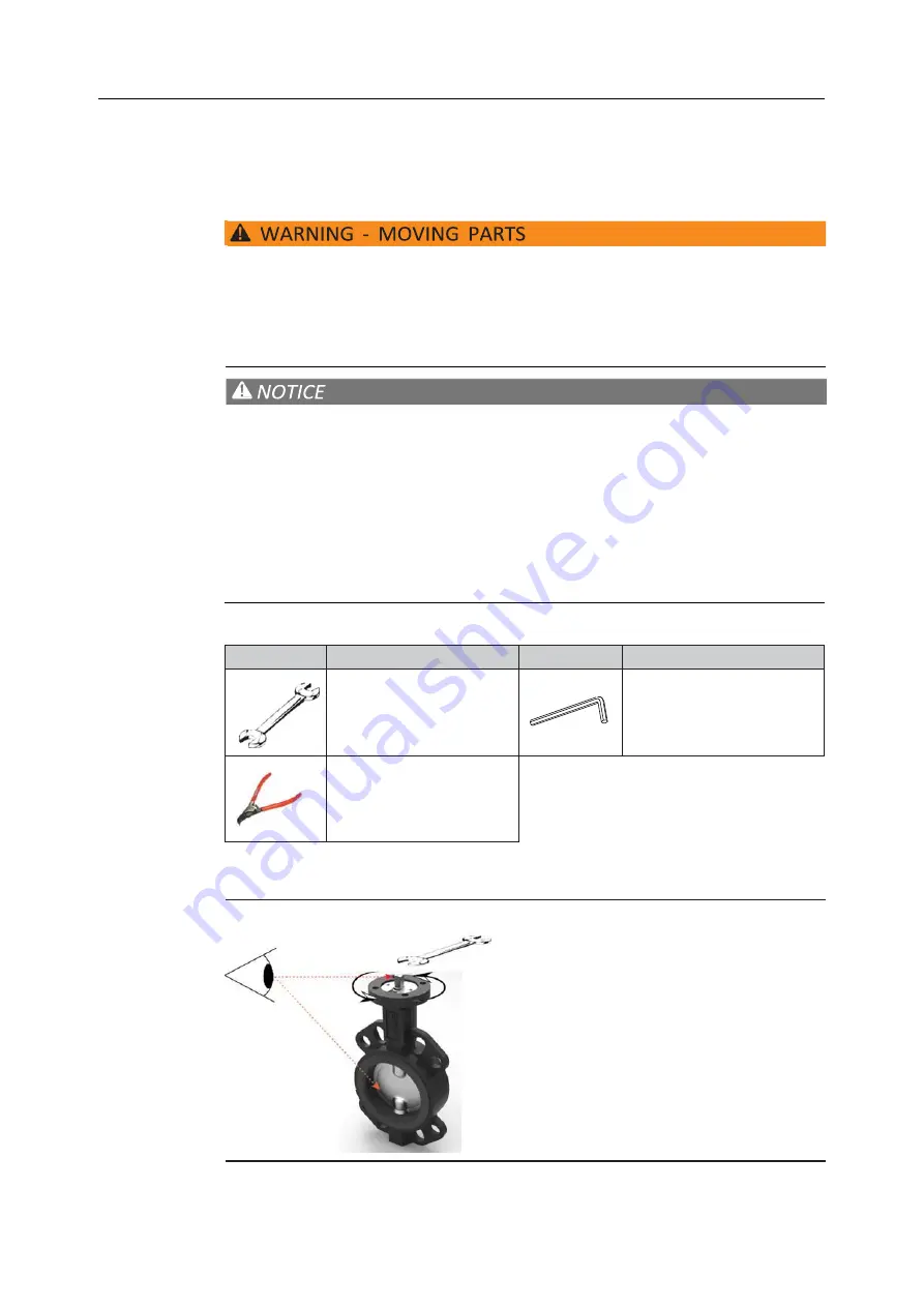
Remove handle nut, handle, lock washer, and etc. from the valve if required.
Ϯ͘
Visually check to make sure the valve is CLOSED.
Figure 9
Valve handle removal


