


Chapter 3 System Configuration
SP-7165/SP-7167 SERIES USER MANUAL
Page: 3-37
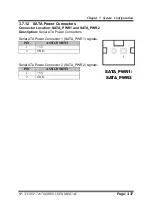
3.7.12 SATA Power Connectors
Connector Location:
SATA_PWR1 and SATA_PWR2
Description:
Serial ATA Power Connectors
Serial ATA Power Connector 1 (SATA_PWR1) signals:
PIN
ASSIGNMENT
1
+5V
2
GND
Serial ATA Power Connector 2 (SATA_PWR2) signals:
PIN
ASSIGNMENT
1
+5V
2
GND
SATA_PWR1/
SATA_PWR2
Summary of Contents for SP-7165
Page 9: ...vi Configuring WatchDog Timer B 25 Flash BIOS Update B 27 ...
Page 16: ...Chapter 2 Getting Started SP 7165 SP 7167 SERIES USER MANUAL Page 2 4 Side View ...
Page 19: ...Chapter 2 Getting Started SP 7165 SP 7167 SERIES USER MANUAL Page 2 7 Side View ...
Page 151: ...Appendix B Technical Summary SP 7165 SP 7167 SERIES USER MANUAL Page B 2 System Block Diagram ...
Page 177: ...Appendix B Technical Summary SP 7165 SP 7167 SERIES USER MANUAL Page B 28 ...


