


Chapter 2 System Configuration
PA-3122 SERIES USER
’
S MANUAL
Page: 2-46
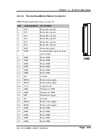
2-5. MSR BOARD COMPONENT LOCATIONS & PIN ASSIGN-
MENT
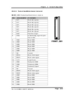
2-5-1. ID TECH
1
7
CN
ID-TECH MSR Board Component Locations
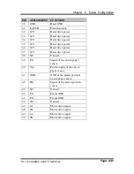
2-5-1-1. Main Connector
CN:
PIN
ASSIGNMENT
PIN
ASSIGNMENT
1
Chassis Ground
5
K-CLK
(Computer connections)
2
P-CLK
(Keyboard connections)
6
K-DATA
(Computer connections)
3
P-DATA
(Keyboard connections)
7
GND
4
+5V Vcc
1
7
CN
Summary of Contents for PA-3122
Page 1: ...USER S MANUAL PA 3122 10 4 POS Terminal Powered by Intel Celeron J1900 Quad Core PA 3122 M1...
Page 165: ...Chapter 3 Software PA 3122 SERIES USER S MANUAL Page 3 106...
Page 189: ...Chapter 4 System Assembly PA 3122 SERIES USER S MANUAL Page 4 6...
Page 191: ...Chapter 4 System Assembly PA 3122 SERIES USER S MANUAL Page 4 8 With MSR 01 Without MSR 02...
Page 193: ...Chapter 4 System Assembly PA 3122 SERIES USER S MANUAL Page 4 10...
Page 195: ...Chapter 4 System Assembly PA 3122 SERIES USER S MANUAL Page 4 12...
Page 198: ...Chapter 4 System Assembly PA 3122 SERIES USER S MANUAL Page 4 15 02 01 Push...
Page 199: ...Chapter 4 System Assembly PA 3122 SERIES USER S MANUAL Page 4 16 Heatsink 05 02 01 03 04...
Page 201: ...Chapter 4 System Assembly PA 3122 SERIES USER S MANUAL Page 4 18...
Page 203: ...Chapter 4 System Assembly PA 3122 SERIES USER S MANUAL Page 4 20...
Page 210: ...Chapter 4 System Assembly PA 3122 SERIES USER S MANUAL Page 4 27 Without VFD Module 01...


