background image


Chapter    2    System Configuration 


PA-3122 SERIES USER

S MANUAL


Page:  2-14


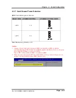
2-2-7.  Cash Drawer Power Selection 


JP29:

 Cash Drawer power selection 


SELECTION  JUMPER SETTING 

JUMPER ILLUSTRATION 

+24V 

1-2 

3

1


JP29 

+12V 

2-3 

3

1


JP29


Note:

 Manufacturing Default is +12V. 


Caution:


1.


Voltage of the external cash drawer port DRW1 is adjustable on BIOS or with the 
corresponding jumper JP29. Either way 

cannot

 be applied simultaneously in case of system 

error, component damage or serious boot failure.   
That is, JP29 will be enabled if DRW1 is disabled on BIOS. 

2.


There is no pin connection for JP29 by default. Refer to 

Voltage Adjust Configuration

 in 

chapter 3 for detailed BIOS setting (BIOS default at 12V). 


Summary of Contents for PA-3122

Page 1: ...USER S MANUAL PA 3122 10 4 POS Terminal Powered by Intel Celeron J1900 Quad Core PA 3122 M1...

Page 2: ...mit in any form or by any means electronic or mechanical including photocopying and recording DISCLAIMER This user s manual is meant to assist users in installing and setting up the system The informa...

Page 3: ...harmful interference in which case the user will be required to correct the interference at his own expense You are cautioned that any change or modifications to the equipment not expressly approve b...

Page 4: ...ent Locations Pin Assignment 2 44 2 5 MSR Board Component Locations Pin Assignment 2 46 CHAPTER 3 SOFTWARE 3 1 Driver 3 2 3 2 Embedded Peripheral Devices 3 8 3 3 API 3 43 3 4 BIOS Operation 3 56 3 5 W...

Page 5: ...nformation for the PA 3122 It also outlines the system specifications Sections included About This Manual POS System Illustration System Specifications Safety precautions Experienced users can jump to...

Page 6: ...al It also includes illustrations and specifications for the whole system The final section of this chapter indicates some safety reminders on how to take care of your system Chapter 2 System Configur...

Page 7: ...hapter 1 Introduction PA 3122 SERIES USER S MANUAL Page 1 3 1 2 POS SYSTEM ILLUSTRATION Top View Bottom View M4 4 100 100 Front View Rear View 286 074 147 098 Side View Quarter View 12 1 135 22 Unit m...

Page 8: ...300mm x 299mm x 135mm Certificate CE FCC Storage SATA 1 x 2 5 HDD or SSD mSATA 1 x SSD I O Ports Serial Port 3 x DB 9 COM2 COM3 COM4 COM1 is optional 5 x wafers on board COM1 1 Co lay with COM1 COM2 1...

Page 9: ...C 4 140 F Humidity 20 90 Optional accessories Customer Display VFD kit 20 columns 2 lines Each column contains 5x7 dots Printer 2 or 3 easy loading thermal printer with auto cutter MSR i Button ISO I...

Page 10: ...lso avoid the system from any heating device Or do not use the PA 3122 when it has been left outdoors in a cold winter day d Bear in mind that the operating ambient temperature is between 0 C and 35 C...

Page 11: ...g agent with a dry cloth b Never use strong agents such as benzene and thinner to clean the surface of the case c If heavy stains are present moisten a cloth with diluted neutral washing agent or alco...

Page 12: ...and connector settings component locations and pin assignment Sections included External I O Port Pin Assignment How to Set Jumpers Component Locations Jumper Settings Mainboard Printer Board peripher...

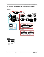
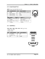
Page 13: ...SYSTEM EXTERNAL I O PORT PIN ASSIGNMENT Rear I O Option1 Option3 Option2 DRW1 eSATA USB 2nd Display Power DC IN COM LAN VGA USB 1 2 3 COM3 COM2 Parallel Port LPT D sub 25 pin Cash Drawer Port from pr...

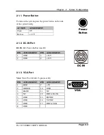
Page 14: ...N ASSIGNMENT Click 0V Release 3 3V 2 1 2 DC IN Port DC IN DC Power In Port rear IO PIN ASSIGNMENT PIN ASSIGNMENT 1 GND 3 24V 2 GND 4 24V 2 1 3 VGA Port VGA VGA Port D Sub 15 pin rear IO PIN ASSIGNMENT...

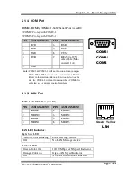
Page 15: ...nnected i Button Refer to the section i Button Function Selection for details COM4 2 will not function when COM4 1 is selected as the printer control interface 2 1 5 LAN Port LAN LAN RJ45 Port rear IO...

Page 16: ...2 Drawer Open 5 NC 3 Drawer Sense 6 GND DRW1 DRW1 1 DRW1 2 Open Write 700 h to I O port 588 h Write 80000003 h to I O Port 588 h Close Write 00 h to I O port 588 h Write 00 h to I O port 588 h 2 1 7 U...

Page 17: ...tional LPT Printer Port D Sub 25 pin co lay with LPT1 PIN ASSIGNMENT PIN ASSIGNMENT 1 STBJ 14 ALFJ 2 PDR0 15 ERRJ 3 PDR1 16 PARR_INITJ 4 PDR2 17 SLCTINJ 5 PDR3 18 GND 6 PDR4 19 GND 7 PDR5 20 GND 8 PDR...

Page 18: ...SP1 SPK1 SLOT1 COM4_2 JP20 JP21 JP22 COM2 COM3 DC5V_PWR1 JP37 JP29 JP5 DC12V_PWR1 LPT1 J2 SATA2 SATA1 JPWR_4P2 JPWR_4P1 TOUCH3 JP14 JP15 JINVDRV1 JINV4 JP4 JP3 JP38 JP39 30 29 1 2 Battery 1 1 1 1 1 3...

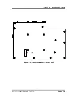
Page 19: ...Chapter 2 System Configuration PA 3122 SERIES USER S MANUAL Page 2 8 SLOT2 1 15 17 51 2 16 18 52 PB 6822 Mainboard Component Locations Rear...

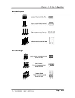
Page 20: ...configuration by opening or closing pins Jumpers can be combined into sets that called jumper blocks When jumpers are all in the block you have to put them together to set up the hardware configurati...

Page 21: ...Chapter 2 System Configuration PA 3122 SERIES USER S MANUAL Page 2 10 Jumper diagrams Jumper settings...

Page 22: ..._ COM4 Note Manufacturing Default is RI for JP_COM1 JP_COM4 and open no connection for JP_COM2 JP_COM3 Caution 1 Voltage of external COM 2 COM3 ports are adjustable on BIOS or with the corresponding j...

Page 23: ...tails refer to COM Port RI Voltage Selection 2 2 4 i Button Connector JI_BUTTON1 i Button Connector PIN ASSIGNMENT 1 COM3_DTR_R_I 2 COM3_RXD_R_I 2 2 5 COM3 i Button Function Selection JP20 JP21 JP22 C...

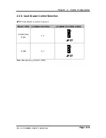
Page 24: ...3122 SERIES USER S MANUAL Page 2 13 2 2 6 Cash Drawer Control Selection JP37 Cash Drawer control connector SELECTION JUMPER SETTING JUMPER ILLUSTRATION Cash Drawer Open 1 2 1 3 JP37 GND 2 3 1 3 JP37...

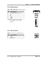
Page 25: ...ult is 12V Caution 1 Voltage of the external cash drawer port DRW1 is adjustable on BIOS or with the corresponding jumper JP29 Either way cannot be applied simultaneously in case of system error compo...

Page 26: ...B2 USB6 USB7 USB 2 0 connector PIN ASSIGNMENT 1 5V Maximum current 0 5A 2 D 3 D 4 GND 5 GND Note USB1 would be used when jumpers JP14 JP15 are set as 1 2 short connected 2 2 9 LED Connector LED1 1 Pow...

Page 27: ...D 3 VCC12 DC5V_PWR1 DC 5Voltage Provider Connector PIN ASSIGNMENT 1 5V 2 GND 2 2 11 Power for Thermal Printer Connector PRT_PWR1 Power for Thermal Printer Connector PIN ASSIGNMENT 1 VCC24SB 2 VCC24SB...

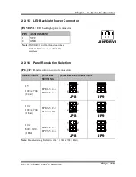
Page 28: ...MENT 1 12V 2 12V 3 GND 4 BRCTR 5 GND 6 LVDS_BKLTEN 2 2 14 LED Backlight Power Control Selection JP12 LED backlight power control connectors for LED backlight panel without power driver built in SELECT...

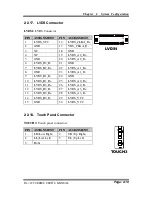
Page 29: ...e set as RS 232 interface 2 2 16 Panel Resolution Selection JP8 JP9 Panel resolution control connectors SELECTION JUMPER SETTING JUMPER ILLUSTRATION 15 1024 x 768 24 bit JP8 1 3 4 6 JP9 3 5 4 6 2 1 6...

Page 30: ...20 LVDS_A2_D 6 LVDS_B2_D 21 GND 7 LVDS_B2_D 22 LVDS_A1_D 8 GND 23 LVDS_A1_D 9 LVDS_B1_D 24 GND 10 LVDS_B1_D 25 LVDS_A0_D 11 LVDS_B3_D 26 LVDS_A0_D 12 LVDS_B3_D 27 LVDS_A3_D 13 LVDS_B0_D 28 LVDS_A3_D...

Page 31: ...Connector JP14 1 2 JP15 1 2 JP38 2 3 JP39 2 3 1 3 JP14 1 3 JP15 3 1 JP38 3 1 JP39 USB Interface JP14 2 3 JP15 2 3 JP38 2 3 JP39 2 3 1 3 JP14 1 3 JP15 3 1 JP38 3 1 JP39 RS 232 Interface JP14 1 2 JP15...

Page 32: ...1 2 1 JP3 Note Manufacturing Default is Normal To clear CMOS data you must power off the computer and set the jumper to Clear CMOS as illustrated above After five to six seconds set the jumper back t...

Page 33: ...connectors PIN ASSIGNMENT PIN ASSIGNMENT 1 G1 5 RX 2 TX 6 RX 3 TX 7 G3 4 G2 Note SATA1 only supports the optional RAID function on board JPWR_4P1 JPWR_4P2 Serial ATA power connectors PIN ASSIGNMENT 1...

Page 34: ...nter Connector LPT1 Printer connector PIN ASSIGNMENT PIN ASSIGNMENT 1 STBJ 14 ALFJ 2 PDR0 15 ERRJ 3 PDR1 16 PAR_INITJ 4 PDR2 17 SLCTINJ 5 PDR3 18 GND 6 PDR4 19 GND 7 PDR5 20 GND 8 PDR6 21 GND 9 PDR7 2...

Page 35: ...30 SMB_CLK 5 Reserved 31 PETn2 6 1 5V 32 SMB_DATA 7 CLKREQ 33 PETp2 8 Reserved 34 GND 9 GND 35 GND 10 Reserved 36 NC 11 REFCLK1 37 GND 12 Reserved 38 NC 13 REFCLK1 39 3 3V 14 Reserved 40 GND 15 GND 4...

Page 36: ...A1_TX 6 1 5V 32 SMB_DATA 7 CLKREQ 33 PETp0 SATA1_TX 8 Reserved 34 GND 9 GND 35 GND 10 Reserved 36 USB_D 11 REFCLK0 37 GND 12 Reserved 38 USB_D 13 REFCLK0 39 3 3V 14 Reserved 40 GND 15 GND 41 3 3V 16 R...

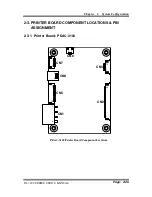
Page 37: ...on PA 3122 SERIES USER S MANUAL Page 2 26 2 3 PRINTER BOARD COMPONENT LOCATIONS PIN ASSIGNMENT 2 3 1 Printer Board PDAC 3100 CN5 CN8 CN7 CN6 CN3 CN1 14 1 1 1 3 7 1 12 CN2 1 50 1 5 1 4 PDAC 3100 Printe...

Page 38: ...L Page 2 27 2 3 1 1 Power Supply Connector CN1 Power supply wafer PIN ASSIGNMENT 1 24V 2 24V 3 GND 4 GND 2 3 1 2 RS 232 Interface Connector CN7 RS 232 interface connector PIN ASSIGNMENT PIN ASSIGNMENT...

Page 39: ...gnal of the hom position sensor 5 2B 1 Auto cutter motor drive signal 6 2B 2 Auto cutter motor drive signal 7 2A 1 Auto cutter motor drive signal 8 2A 2 Auto cutter motor drive signal 9 1B 1 Auto cutt...

Page 40: ...Head drive power 7 DAT Print data output 8 CLK Synchronizing signal for print data transfer 9 GND Head GND 10 GND Head GND 11 GND Head GND 12 GND Head GND 13 GND Head GND 14 GND Head GND 15 NC Unused...

Page 41: ...ad drive power 36 24V Head drive power 37 24V Head drive power 38 NC Unused 39 PS Signal of the out of paper sensor 40 Vps Power supply of the out of paper sensor 41 GND GND of the platen position out...

Page 42: ...IN ASSIGNMENT FUNCTION 1 FEED Feed signal 2 RESET Reset signal 3 GND GND 4 ST1 Status signal 5 ST2 Status signal 6 ST3 Status signal 7 ST4 Status signal 8 GND GND 9 DRS Drawer sensor signal 10 DSW Dra...

Page 43: ...m Configuration PA 3122 SERIES USER S MANUAL Page 2 32 2 3 2 Printer Board MB 1030 1 1 5 1 3 4 CN3 CN2 4 14 1 1 1 50 12 1 1 9 10 2 CN1 CUT_CN1 PRINT_CN1 COM1 USB_CN1 24V_CN1 MB 1030 Printer Board Comp...

Page 44: ...Power Supply Connector 24V_CN1 Power Supply Wafer PIN ASSIGNMENT 1 GND 2 GND 3 24V 4 24V 2 3 2 2 RS 232 Interface Connector COM1 RS 232 Interface Connector PIN ASSIGNMENT PIN ASSIGNMENT 1 NC 6 DSR CTS...

Page 45: ...Head drive power 7 DAT Print data output 8 CLK Synchronizing signal for print data transfer 9 GND Head GND 10 GND Head GND 11 GND Head GND 12 GND Head GND 13 GND Head GND 14 GND Head GND 15 NC Unused...

Page 46: ...ad drive power 36 24V Head drive power 37 24V Head drive power 38 NC Unused 39 PS Signal of the out of paper sensor 40 Vps Power supply of the out of paper sensor 41 GND GND of the platen position out...

Page 47: ...otor drive signal 6 2B 2 Autocutter motor drive signal 7 2A 1 Autocutter motor drive signal 8 2A 2 Autocutter motor drive signal 9 1B 1 Autocutter motor drive signal 10 1B 2 Autocutter motor drive sig...

Page 48: ...signment Connector CN1 Terminal assignment connector PIN ASSIGNMENT FUNCTION 1 FEED Feed signal 2 RESET Reset signal 3 GND GND 4 ST1 Status signal 5 ST2 Status signal 6 ST3 Status signal 7 ST4 Status...

Page 49: ...ystem Configuration PA 3122 SERIES USER S MANUAL Page 2 38 2 3 3 Printer Board MB 1011 MB 1013 CN7 CN3 CN2 CN5 CN1 1 1 14 1 1 12 50 7 4 1 MB 1011 MB 1013 CN8 1 5 MB 1011 MB 1013 Printer Board Componen...

Page 50: ...L Page 2 39 2 3 3 1 Power Supply Connector CN1 Power supply wafer PIN ASSIGNMENT 1 GND 2 GND 3 24V 4 24V 2 3 3 2 RS 232 Interface Connector CN7 RS 232 interface connector PIN ASSIGNMENT PIN ASSIGNMENT...

Page 51: ...Head drive power 7 DAT Print data output 8 CLK Synchronizing signal for print data transfer 9 GND Head GND 10 GND Head GND 11 GND Head GND 12 GND Head GND 13 GND Head GND 14 GND Head GND 15 NC Unused...

Page 52: ...ad drive power 36 24V Head drive power 37 24V Head drive power 38 NC Unused 39 PS Signal of the out of paper sensor 40 Vps Power supply of the out of paper sensor 41 GND GND of the platen position out...

Page 53: ...Signal of the hom position sensor 5 2B 1 Autocutter motor drive signal 6 2B 2 Autocutter motor drive signal 7 2A 1 Autocutter motor drive signal 8 2A 2 Autocutter motor drive signal 9 1B 1 Autocutter...

Page 54: ...IN ASSIGNMENT FUNCTION 1 FEED Feed signal 2 RESET Reset signal 3 GND GND 4 ST1 Status signal 5 ST2 Status signal 6 ST3 Status signal 7 ST4 Status signal 8 GND GND 9 DRS Drawer sensor signal 10 DSW Dra...

Page 55: ...er 2 System Configuration PA 3122 SERIES USER S MANUAL Page 2 44 2 4 VFD BOARD COMPONENT LOCATIONS PIN ASSIGNMENT 2 4 1 VFD Board MB 4103 LD720 JP12V CN1 1 1 16 MB 4103 LD720 VFD Board Component Locat...

Page 56: ...n SELECTION JUMPER SETTING JUMPER ILLUSTRATION OFF 1 2 3 1 JP12V ON 2 3 3 1 JP12V Note Manufacturing Default is ON 2 4 1 2 RS 232 Serial Interface Connector CN1 RS 232 serial interface wafer PIN ASSIG...

Page 57: ...CATIONS PIN ASSIGN MENT 2 5 1 ID TECH 1 7 CN ID TECH MSR Board Component Locations 2 5 1 1 Main Connector CN PIN ASSIGNMENT PIN ASSIGNMENT 1 Chassis Ground 5 K CLK Computer connections 2 P CLK Keyboar...

Page 58: ...SYSKING 1 12 CN SYSKING MSR Board Component Locations 2 5 2 1 Main Connector CN PIN ASSIGNMENT PIN ASSIGNMENT 1 5V Vcc 7 NC 2 K DATA Host to MSR 8 NC 3 K CLK Host to MSR 9 NC 4 P DATA MSR to Keyboard...

Page 59: ...Component Locations 2 5 3 1 Information Button Reader I_BUTTON1 Information button reader PIN ASSIGNMENT 1 I_B1 2 GND 2 5 3 2 Output Connector IO1 Output wafer PIN ASSIGNMENT PIN ASSIGNMENT 1 CLK_KB 7...

Page 60: ...Software Installation Utility VGA Driver Utility LAN Driver Utility Sound Driver Utility Touchsreen Driver Utility Fingerprinter Driver Utility Optional RFID Module Driver Optional Wireless Module Dri...

Page 61: ...Driver Plaform POSReady7 32 bit Main Chip D Driver Plaform Win8 32 64bit Main Chip Intel chipset software installation utility D Driver Plaform POSReady7 32 bit VGA D Driver Plaform Win8 32 64bit VGA...

Page 62: ...f Intel Chipset Components in Device Manager 3 1 2 2 Installation of Intel Chipset Driver The utility pack is to be installed only for POSReady 7 Embedded 8 Industry series and it should be installed...

Page 63: ...ompleted shut down the system and restart PA 3122 for the changes to take effect 3 1 4 LAN Driver Utility PA 3122 is enhanced with LAN function that can support various network adapters Installation p...

Page 64: ...lete the installation 5 Once installation is completed shut down the system and restart PA 3122 for the changes to take effect 3 1 6 Touchscreen Driver Utility The touchscreen driver utility can only...

Page 65: ...tion 5 Once installation is completed shut down the system and restart PA 3122 for the changes to take effect 3 1 8 RFID Module Driver Utility Optional The RFID driver utility can only be installed on...

Page 66: ...9 1 Installation of Wireless Driver To install the wireless driver follow the steps below 1 Connect the USB CD ROM device to PA 3122 and insert the driver disk 2 Enter the Device Embedded Wireless Mod...

Page 67: ...2 1 1 Command List 1 Printer Registry Operation Registry path HKEY_LOCAL_MACHINE SOFTWARE OLEforRetail ServiceOPOS PosPrinter MB1030 Registry Name Default Data Notes Default Value MB1030 OPOS MB1030 1...

Page 68: ...w steps guide you to install the MB1030_OposSetup program Run the setup file MB1030_OposSetup exe located in the Software folder of CD This setup also installs the MB1030 program Follow the wizard ins...

Page 69: ...3 10 3 OPOS Control Object of MB1030 Program a Print tab buttons Button Item Description Printer Normal Print the string b Bitmap tab buttons items Button Item Description Load Load bitmap file Print...

Page 70: ...CE EAN8 EAN13 ITF Codabar Code39 Code93 Code128 Alignment Left center or right Position Print barcode number None Above or Below 4 MB1030 type Key Name Type Default Value Note BaudRate String 115200 U...

Page 71: ...ResultCode Read only 1 0 Supported Properties common long ResultCodeExtended Read only 1 0 Not Applicable Properties common long State Read only 1 0 Supported Properties common string ControlObject De...

Page 72: ...only 1 5 Not Applicable Properties specific bool CapRecDhigh Read only 1 0 Not Applicable Properties Specific bool CapRecDwide Read only 1 0 Not Applicable Properties specific bool CapRecDwideDhigh Re...

Page 73: ...g CharacterSetList Read only 1 0 Not Applicable Properties specific bool CoverOpen Read only 1 0 Not Applicable Properties specific long ErrorLevel Read only 1 1 Not Applicable Properties specific lon...

Page 74: ...e Properties specific long SlpLineHeight R W 1 0 Not Applicable Properties specific long SlpLineSpacing R W 1 0 Not Applicable Properties specific long SlpLineWidth Read only 1 0 Not Applicable Proper...

Page 75: ...1 0 Not Applicable Methods specific CutPaper 1 0 Supported Methods specific RotatePrint 1 0 Supported only 180 Methods specific PrintBarCode 1 0 Supported Methods specific PrintBitmap 1 0 Supported Me...

Page 76: ...MACHINE SOFTWARE OLEforRetail ServiceOPOS LineDisplay Prox PMP4000 Registry Name Default Data Notes Default Value LineDisplay PMP4000 1 BaudRate 9600 BitLength 8 Parity 0 Port COM1 Stop 1 2 OPOS VFD S...

Page 77: ...allation Below steps guide you to install the MB4000_OposSetup program Run the MB4000_OposSetup setup file This setup also installs the Prox PMP4000 program Follow the wizard instructions to complete...

Page 78: ...TextAt Display the string of characters at the specified y and x Clear Clear the current window by displaying Attribute Normal blink reverse blink reverse 4 MB4103 type Key Name Type Default Value Not...

Page 79: ...ommon long ResultCode Read only 1 0 Supported Properties common long ResultCodeExtended Read only 1 0 Not Applicable Properties common long State Read only 1 0 Supported Properties common string Contr...

Page 80: ...y 1 0 Not Applicable Properties specific long Columns Read only 1 0 Not Applicable Properties specific long CursorRow R W 1 0 Not Applicable Properties specific long CursorColumn R W 1 0 Not Applicabl...

Page 81: ...0 Not Applicable Methods specific ClearDescriptors 1 0 Not Applicable Methods specific CreateWindow 1 0 Not Applicable Methods specific DestroyWindow 1 0 Not Applicable Methods specific RefreshWindow...

Page 82: ...ses 1 Installation Below steps guide you to install the MB301X_OposSetup program Run the OPOSMSR_Setup exe setup file This setup also installs the Prox PMP3000 program Follow the wizard instructions t...

Page 83: ...e 3 24 3 Configuration of Prox PMP3000 program a Main screen Control tab items Button Item Description COM dropdown list To set COM port number only for USRT USB interface AutoDisable check box Set au...

Page 84: ...n DecodeData Set decode data properties applicable ParseDecodeData Set parse decode data properties TransmitSentinels Set transmit sentinels properties ErrorReporting Type Card track TracksToRead Trac...

Page 85: ...RIES USER S MANUAL Page 3 26 d Track Data tab items Button Item Description TracksData Row Display data of all tracks Track4 is not applicable e Parsed Data tab items Button Item Description Parsed Da...

Page 86: ...common long OutputID Read only 1 0 Not Applicable Properties common long PowerNotify R W 1 3 Not Applicable Properties common long PowerState Read only 1 3 Not Applicable Properties common long Result...

Page 87: ...string MiddleInitial Read only 1 0 Supported Properties specific string Surname Read only 1 0 Supported Properties specific string Suffix Read only 1 0 Supported Properties specific string ServiceCod...

Page 88: ...SO track data CapJISOne 1 reserved CapJISTwo 1 reserved CapTransmitSentinels 1 Capability for reading Transmit Sentinels Debug 0 Enable the tracing and create a log file Description GIGATMS MSR POS De...

Page 89: ...Enabled R W DeviceEnabled R W FreezeEvents R W OpenResult Read only ResultCode Read only ResultCodeExtended Read only State Read only ControlObjectDescription Read only ControlObjectVersion Read only...

Page 90: ...f support by the driver Notes ServiceCode Read Only Suffix Read Only Surname Read Only Title Read Only Track1Data Read Only Track1DiscretionaryData Read Only Track2Data Read Only Track2DiscretionaryDa...

Page 91: ...nstall the OPOS MSR Register program Insert the setup CD Run the setup file OPOSMSR_Setup exe located in the Software folder of CD This setup also installs the OPOS MSR Tester program Follow the wizar...

Page 92: ...ported Each type support specific MSR readers For more details please refer to the section OPOS MSR Service Object and Method Relations Service Object Right pane The registered MSR with specified devi...

Page 93: ...Chapter 3 Software PA 3122 SERIES USER S MANUAL Page 3 34 c Example 1 MAGTEK USB HID d Example 2 PROMAG MSR MJR PART NO Keyboard mode...

Page 94: ...Object must be checked 4 MJR243 type Key Name Type Default Value Note CapISO string 1 Capability for reading ISO track data CapJISOne string 1 reserved CapJISTwo string 1 reserved CapTransmitSentinels...

Page 95: ...rties common bool CapUpdateStatistics Read only 1 8 Not Applicable Properties common string CheckHealthText Read only 1 0 Not Applicable Properties common bool Claimed Read only 1 0 Supported Properti...

Page 96: ...1 1 Not Applicable Properties specific long ErrorReportType R W 1 2 Not Applicable Properties specific string ExpirationDate Read only 1 0 Supported Properties specific string FirstName Read only 1 0...

Page 97: ...ot Applicable Methods common ClearInput 1 Supported Methods common ClearInput Properties 1 1 Supported Methods common ClearOutput 1 Not Applicable Methods common DirectIO 1 Not Applicable Methods comm...

Page 98: ...m make sure the device name registry information for MSRHK reader has been already created by OPOS MSR Register program 1 Installation The installation of OPOS MSR Tester program goes together with OP...

Page 99: ...ta Text boxes Show the raw and parsed track data Clear Button Clear all the track data in the text boxes Open Button Open the OPOS driver and ready to get track data Close Button Close the OPOS driver...

Page 100: ...Chapter 3 Software PA 3122 SERIES USER S MANUAL Page 3 41 c Example 1 MAGTEK USB HID d Example 2 PROMAG MSR MJR PART NO Keyboard mode...

Page 101: ...Chapter 3 Software PA 3122 SERIES USER S MANUAL Page 3 42 e Example 3 PROMAG MSR PART NO HID mode...

Page 102: ...to control Watchdog Hardware Monitor Hardware Monitor dll Driver to read hardware data multilangXML dll Driver to open XML file Initial xml XML file to initiate the API Package ProxAP exe API program...

Page 103: ...utton to call API Function a Call Cash drawer open event Private Sub cash_btn1_Click ByVal Sender As System Object ByVal e As System EventArgs Handles cash_btn1 Click CashDrawerOpen 1 1 specifies the...

Page 104: ...45 Text1 text cash drawer1 close enter text into textbox End if Receive_Status2 CashDrawerOpen H2 If Receive_Status2 true then Text2 text cash drawer2 open enter text into textbox Else Text2 text cas...

Page 105: ...hort As Boolean Declare Function CashDrawerOpen Lib CashDrawer dll ByVal num_drawer as short As Boolean Call Function Open cash drawer CashDrawerOpen 1 Open cash drawer1 CashDrawerOpen 2 Open cash dra...

Page 106: ...ic extern bool GetCashDrawerStatus DllImport CashDrawer dll EntryPoint CashDrawerOpen Public static extern bool CashDrawerOpen short num_drawer Call Function Open cash drawer1 PortAccess CashDrawerOpe...

Page 107: ...Lib Digital dll As Short Declare Function GPIO_Initial Lib GPIO dll As Long Declare Function GPIO_SetPort Lib GPIO dll ByVal direct As long Declare Function GPIO_Set Lib GPIO dll ByVal dout_value As l...

Page 108: ...USER S MANUAL Page 3 49 3 3 4 Cash Drawer Button Item Description OPEN button Tap to open the cash drawer Cash drawer status will be displayed after OPEN is tapped Drawer is closed as shown Cash Draw...

Page 109: ...chdog The maximum timeout value is 255 seconds or minutes Watchdog Control Timeout Value Simulation timer of the API program the running watchdog timeout will be displayed in seconds It is not as accu...

Page 110: ...oftware PA 3122 SERIES USER S MANUAL Page 3 51 3 3 6 Hardware Monitor Preview Button Item Description Monitor button Tap to get the hardware monitoring values such as the voltages temperatures and fan...

Page 111: ...provided for easy use of the API Package Refer to the main API functions listed as below API Function DLL Cash Drawer CashDrawerOpen GetCashDrawerStatus CashDrawer dll Watchdog WD Watchdog_Set Watchd...

Page 112: ...False 0 on failure Example CashDrawerOpen 0x01 Open the Cash Drawer1 GetCashDrawerStatus bool GetCashDrawerStatus short num_drawer Purpose Get the cash drawer status Value num_drawer 1 Get the Cash Dr...

Page 113: ...ol Watchdog_SetMinSec int kind Purpose Set the unit of time as second minute Value kind 1 Measured in unit of second kind 2 Measured in unit of minute Return True 1 on success False 0 on failure Watch...

Page 114: ...voltage value Value VoltType 81866 0x01 Vcore 0x02 5VSB 0x03 VCC5V 0x04 VCC12 0x05 N A 0x06 N A 0x07 N A Return Float type data on voltage value HMWTemperature_Get float HMWTemperature_Get short Temp...

Page 115: ...firmware based on the UEFI Unified Extensible Firmware Interface Specifications and the Intel Platform Innovation Framework for EFI The UEFI specification defines an interface between an operating sy...

Page 116: ...tup personal password etc which is convenient for modifications and customization of the computer system and allows technicians another method for finding solutions if hardware has any problems The BI...

Page 117: ...f Test POST routines and the following message will appear on the lower screen POST screen As long as this message is present on the screen you may press the Del key the one that shares the decimal po...

Page 118: ...NUAL Page 3 59 BIOS setup program initial screen You may move the cursor by up down keys to highlight the individual menu items As you highlight each item a brief description of the highlighted select...

Page 119: ...current BIOS core version Compliancy No changeable options Displays the current UEFI version Project Version No changeable options Displays the version of the BIOS currently installed on the platform...

Page 120: ...SERIES USER S MANUAL Page 3 61 BIOS Setting Options Description Purpose System Language English BIOS Setup language System Date Month day year Specifies the current date System Time Hour minute second...

Page 121: ...enu F81866 Watchdog Parameters CPU Configuration Sub Menu CPU Configuration Parameters IDE Configuration Sub Menu SATA Configuration Parameters OS Selection Sub Menu OS Selection Voltage RI Adjust Con...

Page 122: ...re Enable Hibernation Disabled Enabled Enables or Disables System ability to Hibernate OS S4 Sleep State This option may be not effective with some OS ACPI Sleep State Suspend Disabled S3 Only Suspend...

Page 123: ...System Temperature No changeable options Displays system s temperature CPU Fan Speed No changeable options Displays fan s speed VCORE No changeable options Displays voltage level of the VCORE in suppl...

Page 124: ...6 Watchdog screen BIOS Setting Options Description Purpose Enable WatchDog Enabled Disable Enable Disable Watch dog timer Watchdog timer unit 1s 60s Select seconds or minutes Count for Timer Seconds M...

Page 125: ...CPU Information Sub Menu Report CPU Information CPU Speed No changeable options Reports the current CPU Speed 64 bit No changeable options Reports if 64 bit is supported by processor Active Processor...

Page 126: ...SERIES USER S MANUAL Page 3 67 BIOS Setting Options Description Purpose Intel Virtualization Technology Disabled Enabled When enabled a VMM can utilize the additional hardware capabilities provided b...

Page 127: ...No changeable options Reports the maximum CPU Speed Min CPU Speed No changeable options Reports the minimum CPU Speed Processor Cores No changeable options Displays number of physical cores in process...

Page 128: ...MANUAL Page 3 69 BIOS Setting Options Description Purpose L1 Code Cache No changeable options Displays size of L1 Code Cache L2 Cache No changeable options Displays size of L2 Cache L3 Cache No chang...

Page 129: ...ATA Device SATA Test Mode Disabled Enabled Enable or disable SATA Test Mode SATA Speed Support GEN1 GEN2 Gen1 mode sets the device to 1 5 Gbit s speed Gen2 mode sets the device to 3 Gbit s speed in ca...

Page 130: ...evice HotPlug SATA Port 1 Note 2 Disabled Enabled Enable or disable SATA port 1 Device SATA Port 1 HotPlug Disabled Enabled Enable or disable SATA port 1 Device HotPlug SATA Port 0 drive Displays the...

Page 131: ...ter 3 Software PA 3122 SERIES USER S MANUAL Page 3 72 3 4 4 6 OS Selection OS Selection screen BIOS Setting Options Description Purpose OS Selection Windows 8 x Android Windows7 Operation System Selec...

Page 132: ...age Adjust Configuration Voltage Adjust Configuration screen BIOS Setting Options Description Purpose COM1 Select Disabled RI 12V 5V Select COM1 Port voltage COM2 Select Disabled RI 12V 5V Select COM2...

Page 133: ...tware PA 3122 SERIES USER S MANUAL Page 3 74 BIOS Setting Options Description Purpose COM4 Select Disabled RI 12V 5V Select COM4 Port voltage Cash drawer Cash drawer 12V Cash drawer 24V Select Cash dr...

Page 134: ...abled Enabled Disable or Enable CSM support CSM16 Module Version No changeable options Displays the current CSM Compatibility Support Module version GateA20 Active Upon Request Always Select Gate A20...

Page 135: ...ilter UEFI and Legacy Legacy only UEFI only This option controls what kind of devices system can boot Network Do not launch UEFI only Legacy only Legacy first UEFI first Controls the execution of UEFI...

Page 136: ...ons Displays number of available USB devices Legacy USB Support Disabled Enabled Auto Enables support for legacy USB USB3 0 Support Disabled Enabled Enable Disable USB3 0 XHCI Controller support EHCI...

Page 137: ...out Device power up delay Auto Manual Maximum time the device will take before it properly reports itself to the Host Controller Auto uses default value for a Root port it is 100 ms for a Hub port the...

Page 138: ...ption Purpose Active Serial Port 1 Sub menu Set Parameters for COM1 Active Serial Port 2 Sub menu Set Parameters for COM2 Active Serial Port 3 Sub menu Set Parameters for COM3 Active Serial Port 4 Sub...

Page 139: ...Enable or disable serial port 1 Logical device setting No changeable options Displays current settings of serial port 2 Possible Use Automatic Settings IO 3F8h IRQ 4 DMA IO 3F8h IRQ 3 4 5 6 7 9 10 11...

Page 140: ...Enable or disable serial port 2 Logical device setting No changeable options Displays current settings of serial port 2 Possible Use Automatic Settings IO 2F8h IRQ 3 DMA IO 3F8h IRQ 3 4 5 6 7 9 10 11...

Page 141: ...al device setting No changeable options Displays current settings of serial port 3 Possible Use Automatic Settings IO 3E8h IRQ 7 DMA IO 3F8h IRQ 3 4 5 6 7 9 10 11 12 DMA IO 2F8h IRQ 3 4 5 6 7 9 10 11...

Page 142: ...al device setting No changeable options Displays current settings of serial port 4 Possible Use Automatic Settings IO 2E8h IRQ 7 DMA IO 3F8h IRQ 3 4 5 6 7 9 10 11 12 DMA IO 2F8h IRQ 3 4 5 6 7 9 10 11...

Page 143: ...This Device Disabled Enabled Enable or disable the printer port Logical device setting No changeable options Displays current settings of the printer port Possible Use Automatic Settings IO 378h IRQ...

Page 144: ...and EPP 1 9 Mode ECP and EPP 1 7 Mode Selects the mode for the parallel port Not available if the parallel port is disabled SPP is Standard Parallel Port mode a bi directional mode for printers EPP is...

Page 145: ...BIOS Setting Options Description Purpose Use This Device Disabled Enabled Enable or disable the PS2 Logical device setting Current No changeable options Displays current settings of the printer port P...

Page 146: ...S USER S MANUAL Page 3 87 3 4 5 Chipset Chipset screen BIOS Setting Options Description Purpose North Bridge Sub menu Sets Parameter for North Bridge configuration South Bridge Sub menu Sets Parameter...

Page 147: ...h Bridge North Bridge screen BIOS Setting Options Description Purpose Intel IGD Configuration Sub menu Configure Graphic Settings Memory Information No changeable options Displays the DRAM information...

Page 148: ...S Intel IGD Configuration No changeable options Displays the IGD information on platform Integrated Graphics Device Disabled Enabled Enable Enable Integrated Graphics Device IGD when selected as the P...

Page 149: ...PA 3122 SERIES USER S MANUAL Page 3 90 BIOS Setting Options Description Purpose DVMT Pre Allocated 32M 64M 96M 128M 256M 512M Select DVMT 5 0 Pre Allocated Fixed Graphics Memory size used by the Inter...

Page 150: ...idge South Bridge screen BIOS Setting Options Description Purpose USB Configuration Sub menu Configure USB parameters PCI Express Configuration Sub menu Configure PCH PCIE parameters High Precision Ti...

Page 151: ...ower Loss Power Off Power On Last State Select AC power state when power is re applied after a power failure Power Off keeps the power off till the power button is pressed Power On makes system power...

Page 152: ...Enables Enhanced Host Controller Interface 1 for high speed USB functions USB 2 0 USB Per Port Control Disabled Enabled Enabled or Disabled per USB port USB Port 0 Disabled Enabled Enabled or Disable...

Page 153: ...Note 1 Disabled Enabled Enabled or Disabled PCI Express port 0 speed Auto Gen1 Gen2 Selection PCI Express port 0 Speed PCI Express Port 2 For mini PCI E Disabled Enabled Enabled or Disabled PCI Expres...

Page 154: ...Chapter 3 Software PA 3122 SERIES USER S MANUAL Page 3 95 BIOS Setting Options Description Purpose Speed Auto Gen1 Gen2 Selection PCI Express port 3 Speed...

Page 155: ...n BIOS Setting Options Description Purpose Administrator Password Password can be 3 20 alphanumeric characters Specifies the administrator password User Password Password can be 3 20 alphanumeric char...

Page 156: ...econds to wait for setup activation key Bootup NumLock State On Off Specifies the power on state of the NumLock Key Quiet Boot Disabled Enabled Enable Disable Quiet Boot Options Boot Option 1 n Drive...

Page 157: ...3122 SERIES USER S MANUAL Page 3 98 3 4 7 1 Hard Drive BBS Priorities Hard drive BBS priorities screen BIOS Setting Options Description Purpose Boot Option 1 n Drive s Disabled Change the boot order...

Page 158: ...anges and Exit No changeable options Exits without saving any changes made in BIOS settings Save Changes and Reset No changeable options Saves the changes in NVRAM and resets Discard Changes and Reset...

Page 159: ...igure the configuration registers The chip selects the Logical Device and activates the desired Logical Devices through Extended Function Index Register EFIR and Extended Function Data Register EFDR T...

Page 160: ...ended function mode mov dx 2eh mov al 87h out dx al out dx al Select Logical Device 7 of watchdog timer mov al 07h out dx al inc dx mov al 07h out dx al Enable Watch dog feature mov al 030h out dx al...

Page 161: ...IES USER S MANUAL Page 3 102 in al dx and al 30h out dx al Set timeout interval as 30seconds and start counting dec dx mov al 0f6h out dx al inc dx mov al 1Eh out dx al Exit the extended function mode...

Page 162: ...AMI flash utility AFUDOS exe V3 03 into the bootable device 4 Make sure the target system can first boot to the bootable device a Connect the bootable USB device b Turn on the computer and press Del o...

Page 163: ...AMI firmware update utility the command line is shown as below AFUDOS ROM File Name option1 option2 You can type AFUDOS to see all the definition of each control options The recommended options for B...

Page 164: ...update process status and its percentage Beware Do not turn off or reset your computer before the update is complete or it may crash the BIOS ROM and make the system unable to boot up next time The wh...

Page 165: ...Chapter 3 Software PA 3122 SERIES USER S MANUAL Page 3 106...

Page 166: ...series PCI Express Root Port 2 0F4A 18 Intel Pentium processor N and J series Intel Celeron processor N and J series PCI Express Root Port 3 0F4C 19 Intel Pentium processor N and J series Intel Celer...

Page 167: ...ft ACPI Compliant System 104 Microsoft ACPI Compliant System 105 Microsoft ACPI Compliant System 106 Microsoft ACPI Compliant System 107 Microsoft ACPI Compliant System 108 Microsoft ACPI Compliant Sy...

Page 168: ...rosoft ACPI Compliant System 136 Microsoft ACPI Compliant System 137 Microsoft ACPI Compliant System 138 Microsoft ACPI Compliant System 139 Microsoft ACPI Compliant System 140 Microsoft ACPI Complian...

Page 169: ...rosoft ACPI Compliant System 168 Microsoft ACPI Compliant System 169 Microsoft ACPI Compliant System 170 Microsoft ACPI Compliant System 171 Microsoft ACPI Compliant System 172 Microsoft ACPI Complian...

Page 170: ...rosoft ACPI Compliant System 264 Microsoft ACPI Compliant System 265 Microsoft ACPI Compliant System 266 Microsoft ACPI Compliant System 267 Microsoft ACPI Compliant System 268 Microsoft ACPI Complian...

Page 171: ...rosoft ACPI Compliant System 296 Microsoft ACPI Compliant System 297 Microsoft ACPI Compliant System 298 Microsoft ACPI Compliant System 299 Microsoft ACPI Compliant System 300 Microsoft ACPI Complian...

Page 172: ...rosoft ACPI Compliant System 328 Microsoft ACPI Compliant System 329 Microsoft ACPI Compliant System 330 Microsoft ACPI Compliant System 331 Microsoft ACPI Compliant System 332 Microsoft ACPI Complian...

Page 173: ...rosoft ACPI Compliant System 360 Microsoft ACPI Compliant System 361 Microsoft ACPI Compliant System 362 Microsoft ACPI Compliant System 363 Microsoft ACPI Compliant System 364 Microsoft ACPI Complian...

Page 174: ...rosoft ACPI Compliant System 392 Microsoft ACPI Compliant System 393 Microsoft ACPI Compliant System 394 Microsoft ACPI Compliant System 395 Microsoft ACPI Compliant System 396 Microsoft ACPI Complian...

Page 175: ...rosoft ACPI Compliant System 424 Microsoft ACPI Compliant System 425 Microsoft ACPI Compliant System 426 Microsoft ACPI Compliant System 427 Microsoft ACPI Compliant System 428 Microsoft ACPI Complian...

Page 176: ...rosoft ACPI Compliant System 456 Microsoft ACPI Compliant System 457 Microsoft ACPI Compliant System 458 Microsoft ACPI Compliant System 459 Microsoft ACPI Compliant System 460 Microsoft ACPI Complian...

Page 177: ...rosoft ACPI Compliant System 488 Microsoft ACPI Compliant System 489 Microsoft ACPI Compliant System 490 Microsoft ACPI Compliant System 491 Microsoft ACPI Compliant System 492 Microsoft ACPI Complian...

Page 178: ...liant System 510 Microsoft ACPI Compliant System 511 Microsoft ACPI Compliant System 4294967291 Intel HD Graphics 4294967292 Intel USB 3 0 eXtensible Host Controller 0100 Microsoft 4294967293 Intel Tr...

Page 179: ...0004F Motherboard resources 0x00000050 0x00000053 System timer 0x00000060 0x00000060 Standard PS 2 Keyboard 0x00000061 0x00000061 Motherboard resources 0x00000063 0x00000063 Motherboard resources 0x00...

Page 180: ...resources 0x00000680 0x0000069F Motherboard resources 0x00000A00 0x00000A0F Motherboard resources 0x00000A10 0x00000A1F Motherboard resources 0x00000A20 0x00000A2F Motherboard resources 0x00000D00 0x...

Page 181: ...SIGNMENT 0x0000F060 0x0000F063 Intel Pentium processor N and J series Intel Celeron processor N and J series AHCI 0F23 0x0000F070 0x0000F077 Intel Pentium processor N and J series Intel Celeron proces...

Page 182: ...CIe GBE Family Controller 0xD0600000 0xD0603FFF Intel Pentium processor N and J series Intel Celeron processor N and J series PCI Express Root Port 4 0F4E 0xFED00000 0xFED003FF High precision event ti...

Page 183: ...SSIGNMENT 0xE00000D0 0xE00000DB Intel Sideband Fabric Device 0xFF000000 0xFFFFFFFF Intel 82802 Firmware Hub Device 0xA0000 0xBFFFF PCI Express Root Complex 0xA0000 0xBFFFF Intel HD Graphics 0xC0000 0x...

Page 184: ...umbers of the PA 3122 system Sections included Exploded Diagram for System Top Case Exploded Diagram for System LCD Panel Exploded Diagram for System Bottom Case Exploded Diagram for MSR Exploded Diag...

Page 185: ...Chapter 4 System Assembly PA 3122 SERIES USER S MANUAL Page 4 2 EXPLODED DIAGRAM FOR SYSTEM TOP CASE Open the System Top Module 01 02 03 04...

Page 186: ...Chapter 4 System Assembly PA 3122 SERIES USER S MANUAL Page 4 3 02 01 Remove Cable x 3 Remove Cable x 4 1 Rotate 45 2 Push 3 Remove as the arrow indicates...

Page 187: ...Chapter 4 System Assembly PA 3122 SERIES USER S MANUAL Page 4 4 With i Button 05 07 08 09 10 06 02 01 03 04...

Page 188: ...Chapter 4 System Assembly PA 3122 SERIES USER S MANUAL Page 4 5 With Fingerprinter 05 07 08 06 02 01 03 04 12 09 11 13 10...

Page 189: ...Chapter 4 System Assembly PA 3122 SERIES USER S MANUAL Page 4 6...

Page 190: ...Chapter 4 System Assembly PA 3122 SERIES USER S MANUAL Page 4 7 With MSR 05 07 08 06 02 01 03 04...

Page 191: ...Chapter 4 System Assembly PA 3122 SERIES USER S MANUAL Page 4 8 With MSR 01 Without MSR 02...

Page 192: ...Chapter 4 System Assembly PA 3122 SERIES USER S MANUAL Page 4 9 EXPLODED DIAGRAM FOR SYSTEM LCD PANEL 05 02 01 03 04 07 08 06 09 10 Back side...

Page 193: ...Chapter 4 System Assembly PA 3122 SERIES USER S MANUAL Page 4 10...

Page 194: ...Chapter 4 System Assembly PA 3122 SERIES USER S MANUAL Page 4 11 05 07 08 06 02 01 03 04 12 09 11 13 10 Back side...

Page 195: ...Chapter 4 System Assembly PA 3122 SERIES USER S MANUAL Page 4 12...

Page 196: ...Chapter 4 System Assembly PA 3122 SERIES USER S MANUAL Page 4 13 EXPLODED DIAGRAM FOR SYSTEM BOTTOM CASE 05 06 02 02 01 03 04...

Page 197: ...Chapter 4 System Assembly PA 3122 SERIES USER S MANUAL Page 4 14 Printer Control Board 05 07 08 06 02 01 03 04 Printer Box...

Page 198: ...Chapter 4 System Assembly PA 3122 SERIES USER S MANUAL Page 4 15 02 01 Push...

Page 199: ...Chapter 4 System Assembly PA 3122 SERIES USER S MANUAL Page 4 16 Heatsink 05 02 01 03 04...

Page 200: ...Chapter 4 System Assembly PA 3122 SERIES USER S MANUAL Page 4 17 Mainboard 02 05 07 08 06 01 03 04...

Page 201: ...Chapter 4 System Assembly PA 3122 SERIES USER S MANUAL Page 4 18...

Page 202: ...Chapter 4 System Assembly PA 3122 SERIES USER S MANUAL Page 4 19 EXPLODED DIAGRAM FOR PRINTER 3 Inch Printer 05 07 08 06 02 01 03 04 09 11 10...

Page 203: ...Chapter 4 System Assembly PA 3122 SERIES USER S MANUAL Page 4 20...

Page 204: ...Chapter 4 System Assembly PA 3122 SERIES USER S MANUAL Page 4 21 3 Inch Printer Cover 05 07 08 06 02 01 03 04 09 10...

Page 205: ...Chapter 4 System Assembly PA 3122 SERIES USER S MANUAL Page 4 22 2 Inch Printer 05 07 08 06 02 01 03 04 09 11 10...

Page 206: ...Chapter 4 System Assembly PA 3122 SERIES USER S MANUAL Page 4 23 2 Inch Printer Cover 05 07 08 06 02 01 03 04 09 10...

Page 207: ...Chapter 4 System Assembly PA 3122 SERIES USER S MANUAL Page 4 24 With Paper Holder 02 01 Without Paper Holder 03...

Page 208: ...Chapter 4 System Assembly PA 3122 SERIES USER S MANUAL Page 4 25 EXPLODED DIAGRAM FOR MSR 02 01 03 04...

Page 209: ...Chapter 4 System Assembly PA 3122 SERIES USER S MANUAL Page 4 26 EXPLODED DIAGRAM FOR VFD VFD Module 05 02 01 03 04...

Page 210: ...Chapter 4 System Assembly PA 3122 SERIES USER S MANUAL Page 4 27 Without VFD Module 01...

Page 211: ...Chapter 4 System Assembly PA 3122 SERIES USER S MANUAL Page 4 28 EXPLODED DIAGRAM FOR HDD 02 01 03 04 Do not cover breather hole...

Reviews: