background image

 
ILX56-PBS 


Setup  

ControlLogix® Platform  


User Manual 


Page 25 of 87 


  Module Download  

 
Once the ILX56-PBS configuration has been completed, it must be downloaded to the module. 
The configured IP address of the Logix Controller or the 1756 Ethernet card will be used to 
connect to the module, as set in the “Connection Path”. 
 

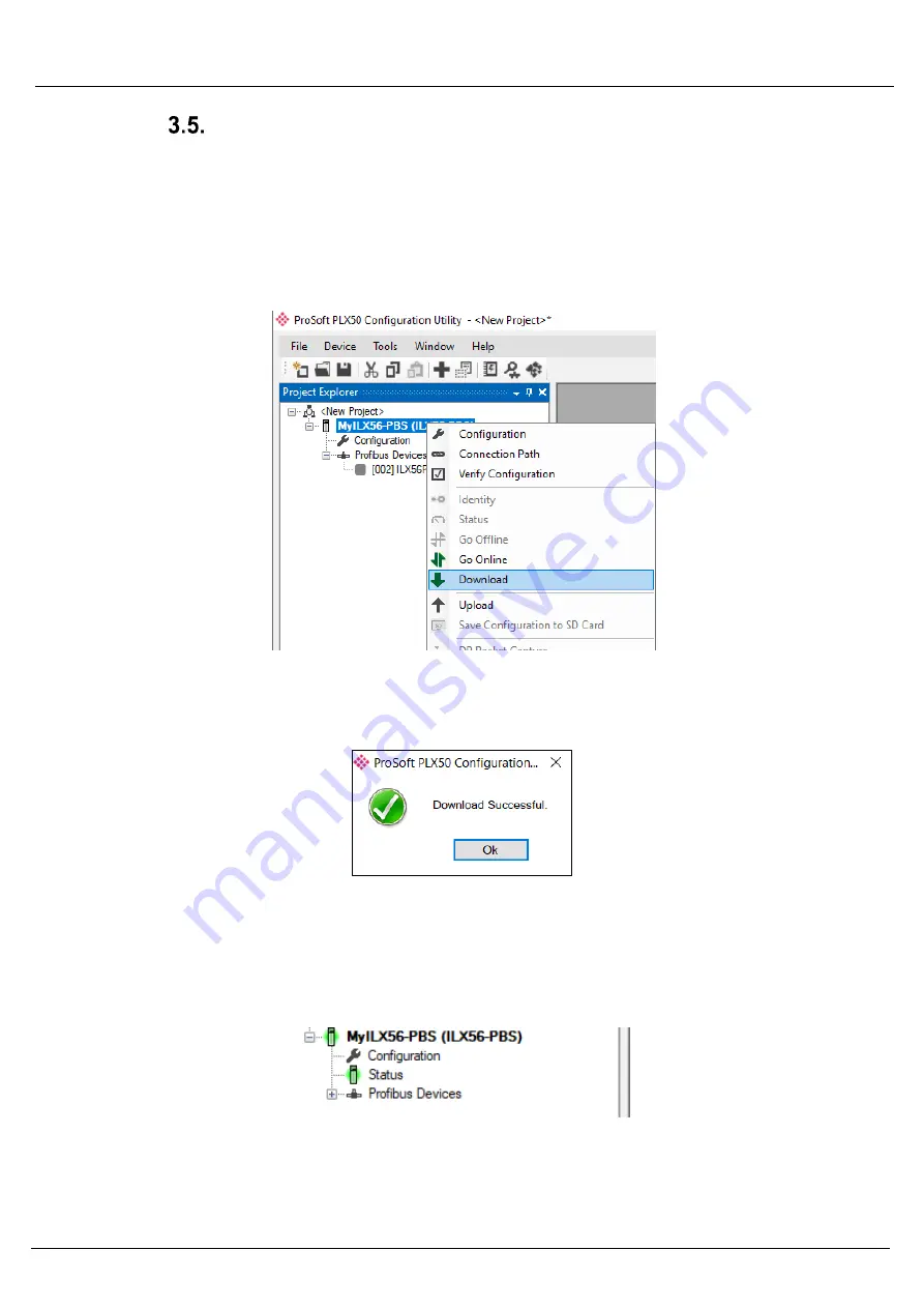
To initiate the download, right-click on the module and select the Download option. 


Figure 3.16 - Selecting Download 

Once complete, the user will be notified that the download was successful. 


Figure 3.17 - Successful download 

Within the PLX50 Configuration Utility, the module will be in the Online state. This is 
indicated by the green circle around the module. The module is now configured and in 
an operational state.  


Figure 3.18 - Module online 


Summary of Contents for ILX56-PBS

Page 1: ...ILX56 PBS PROFIBUS DPV1 Slave ControlLogix Platform May 19 2020 User Manual...

Page 2: ...uding illustrations specifications and dimensions may contain technical inaccuracies or typographical errors ProSoft Technology makes no warranty or representation as to its accuracy and assumes no li...

Page 3: ...onents O O O O O O SJ T 11364 This table is made per guidance of SJ T 11364 O GB T 26572 O Indicates that this hazardous substance contained in all of the homogeneous materials for the part is below t...

Page 4: ...2 ILX56 PBS Parameters 14 General 14 PROFIBUS Slave Mode 15 Logix 16 Adding PROFIBUS DP Devices 17 General 18 PROFIBUS Configuration 19 DPV1 20 User Parameters 21 Slot Configuration 21 Start up Parame...

Page 5: ...ming 46 Upgrading Firmware 48 5 Diagnostics 50 LEDs 50 Module Status Monitoring 52 ILX56 PBS Status 53 General 53 Slave Status 55 Logix Statistics 56 ILX56 PBS Emulated Slave Device Status 57 PROFIBUS...

Page 6: ...68 8 ILX56 PBS Quickstart 69 GSD File Management Tool Installation 69 Creating a New Project 70 PROFIBUS Configuration 71 Logix Configuration 71 Adding a PROFIBUS Slave 72 Downloading the Configurati...

Page 7: ...Slave module The ILX56 PBS slots into a 1756 ControlLogix backplane and allows the user to interface PROFIBUS DP to a ControlLogix controller via the ControlLogix backplane The ILX56 PBS can operate a...

Page 8: ...The data will be formatted into the engineering units for use in a ControlLogix platform by using the automatically generated mapping imports for Logix User Defined Data Types UDTs Each emulated slave...

Page 9: ...85 PROFIBUS DP port at the front of the module NOTE All required power for the module is derived from the ControlLogix backplane The module provides 3 diagnostic LEDs and a 4 character alpha numeric L...

Page 10: ...ccasion when a firmware update was interrupted at a critical stage DIP Switch 2 Used to prevent changes to the configuration Table 2 1 DIP Switch Settings PROFIBUS DP Port RS485 The PROFIBUS DP port u...

Page 11: ...stall Configuration Software All the network setup and configuration of the module is achieved by means of the ProSoft PLX50 Configuration Utility This software can be downloaded from http www prosoft...

Page 12: ...w Project Before the user can configure the module a new PLX50 Configuration Utility project must be created 1 Under the File menu select New Figure 3 2 Creating a new project 2 A new device can now b...

Page 13: ...ton Figure 3 4 ILX56 PBS 4 The device will appear in the Project Explorer tree as shown below and its configuration window opened The device configuration window can be reopened by either double click...

Page 14: ...and selecting Configuration Figure 3 6 ILX56 PBS General configuration The General configuration consists of the following parameters Parameter Description Instance Name This parameter is a user defi...

Page 15: ...selecting Configuration Figure 3 7 ILX56 PBS PROFIBUS configuration Slave Mode The PROFIBUS slave configuration consists of the following parameters Parameter Description BAUD Rate Baud Rate in Kbps...

Page 16: ...input and 0 byte configuration NOTE This value must match the same number of connections configured in the Logix IO tree Controller Path This is the CIP path to the Logix controller This path will be...

Page 17: ...US device can then be configured This is done by right clicking on the PROFIBUS Devices item in the tree and selecting Add PROFIBUS Device Figure 3 9 Adding a PROFIBUS Field Device When adding a PROFI...

Page 18: ...ble clicking on the slave device in the tree or right clicking the slave device and selecting Configuration Figure 3 10 Device General configuration parameters The General configuration consists of th...

Page 19: ...ce in the tree or right clicking the slave device and selecting Configuration Figure 3 11 Device PROFIBUS configuration parameters The PROFIBUS configuration consists of the following parameters Param...

Page 20: ...ice DPV1 configuration parameters The DPV1 configuration consists of the following parameters Parameter Description Enable DPV1 Indicates if the slave supports DPV1 Class 1 access read and write or al...

Page 21: ...meters The User Parameters tab is not used for the ILX56 PBS Slot Configuration The PROFIBUS Input Output Module can be added in Slot Configuration tab Slot data point selectable sizes are as follows...

Page 22: ...ILX56 PBS Setup ControlLogix Platform User Manual Page 22 of 87 Start up Parameters The Start up Parameters tab is not used for the ILX56 PBS...

Page 23: ...ot number to which the PROFIBUS DP transaction will be directed Index The Index number to which the PROFIBUS DP transaction will be directed Size The size bytes of the transaction Functions The Functi...

Page 24: ...r than 4 or the alarm triggering will not execute Figure 3 15 Device DPV1 Alarms configuration parameters Logix The DPV1 configuration consists of the following parameters Parameter Description Size T...

Page 25: ...odule as set in the Connection Path 1 To initiate the download right click on the module and select the Download option Figure 3 16 Selecting Download 2 Once complete the user will be notified that th...

Page 26: ...le AOP The user will first need to install the ILX56 PBS AOP before the module can be added to the Logix I O tree Download the AOP from www prosoft technology com Once downloaded extract the zip file...

Page 27: ...pen specify the Name and Slot to complete the instantiation Figure 3 21 Module instantiation 4 Once the instantiation is complete the ILX56 PBS module will appear in the Logix IO tree Figure 3 22 Logi...

Page 28: ...nfiguration Utility project has been defined the user can Browse for an existing PLX50 Configuration Utility project If no PLX50 Configuration Utility project has been defined the user can enter the p...

Page 29: ...enerate Logix L5X option NOTE The user will need to ensure that the Logix Base Tag is correct for the generated Logix L5X code to work The base tag will be the tag name for the module input and output...

Page 30: ...ote Rack Module Location If the module is in a remote rack the user will need to enter the Logix Base Tag based on the name of the remote rack see the example below Figure 3 27 Logix Base tag assignme...

Page 31: ...In the PLX50 Configuration Utility right click on the ILX56 PBS item in the tree and select Generate Logix L5X Figure 3 29 Selecting Generate Logix L5X 2 The user will then be prompted to select a su...

Page 32: ...Routine Figure 3 31 Importing the L5X file into Studio 5000 4 In the file open dialog select the newly created L5X file and click OK The import will create the following Mapping Routine Multiple UDT U...

Page 33: ...ILX56 PBS Setup ControlLogix Platform User Manual Page 33 of 87 Figure 3 33 Imported Logix Objects...

Page 34: ...e structure of which comprises the following Input Status Status related to slave device Input Data As specified in the Input Data Points in the Slot configuration Output Control Used to trigger alarm...

Page 35: ...user can copy the required firmware which can be downloaded from www prosoft technology com onto the root directory of the SD Card Figure 3 36 SD Card Firmware file NOTE If more than one firmware file...

Page 36: ...to the SD Card root directory in one of two ways Figure 3 37 SD Card Configuration file Manual Copy Once the user has created the needed application configuration in the PLX50CU the configuration can...

Page 37: ...gure 3 39 Configuration Export for SD Card NOTE The filename of the configuration file must not be changed NOTE If more than one configuration file with different configuration signatures of the same...

Page 38: ...ad the configuration onto the SD Card using the Save Configuration to SD Card option in PLX50CU This will copy the module s current configuration directly to the SD Card without the need to remove it...

Page 39: ...definitions for the tags in the General Status UDT created by the PLX50CU Figure 4 1 Logix General Status tags Tag Description ConnectionFaulted Indication of backplane connection fault Each backplane...

Page 40: ...ecipher between ILX56 PBM in master mode or slave mode 1 The ILX56 PBS will always have this bit on 0 The ILX56 PBS should never be in state where this bit is 0 ControllerRun The connected Logix contr...

Page 41: ...n alarm pending Bit 0 Node 0 has an alarm pending Bit 1 Node 1 has an alarm pending Bit 126 Node 126 has an alarm pending DeviceDiagnosticPendingFlags Indicates the nodes that have diagnostics pending...

Page 42: ...a exchange Each bit represents a node When the specific bit is set 1 then the device if configured will exchange data with the PROFIBUS master When the bit is off 0 the device does exchange data with...

Page 43: ...vice is active and exchanging data 0 Device is not exchanging data The user must ensure that all application code making use of data from a slave device first checks that the DataExchangeActive bit is...

Page 44: ...ding OutputAssemblyNodeAddrMismatch This bit indicates that there is a mismatch between the actual device station address and the expected Logix mapping station address 0 Station address matches 1 Sta...

Page 45: ...vice Output tags DPV1 Class 1 Messaging MS1 The ILX56 PBS supports DPV1 Class 1 MS1 messaging See the DPV1 Objects in the PLX50 Configuration Utility device configuration section for more information...

Page 46: ...time To trigger an alarm notification for the PROFIBUS Master the user will need to toggle from 0 to 1 the AlarmTrigger tag as shown below Figure 4 5 ILX56 PBS Slave Alarm Trigger Once the alarm has...

Page 47: ...m 3 Pull_Alarm 4 Plug_Alarm Alarm Slot 2 1 Refer to the PROFIBUS Specification EN 50170 for information regarding the diagnostics Alarm Specifier 3 1 Refer to the PROFIBUS Specification EN 50170 for i...

Page 48: ...ration Utility allows the user to upgrade the module firmware in the field 1 In the PLX50 Configuration Utility go to the Tool menu and select the DeviceFlash option Figure 4 8 DeviceFlash Tool 2 The...

Page 49: ...et Browser dialog Figure 4 10 Select the ILX56 PBS module 4 Once firmware upgrade is complete the Device Flash tool will provide the details of the updated module Figure 4 11 ILX56 PBS successfully up...

Page 50: ...ast one slave has not been configured properly and is not exchanging DPV0 data Flashing Green All slaves are successfully exchanging DPV0 data and the DP network operational state is CLEAR Solid Green...

Page 51: ...onal mode CLEAR mode The PROFIBUS network is in CLEAR operational mode Device Fault At least one slave device is not operating correctly Comms Fault Communication fault e g bus cable has been unplugge...

Page 52: ...ssed in full by the PLX50 Configuration Utility To view the module s status in the PLX50 Configuration Utility environment the ILX56 PBS must be online If the module is not already online following a...

Page 53: ...f the ILX56 PBS can be opened by either double clicking on the Status item in the Project Explorer tree or by right clicking on the module and selecting Status Figure 5 3 Selecting ILX56 PBS online St...

Page 54: ...ce Error One or more PROFIBUS devices not communicating Master Node N A BAUD Rate The BAUD Rate of the PROFIBUS network IO bytes second The number of process variable bytes being exchanged between the...

Page 55: ...state of the PROFIBUS Network is CLEAR Comms State OK All configured slaves are operating correctly Failure At least one of the configured devices are not operating correctly Slave Count Number of sl...

Page 56: ...iolation Errors The number of tag read and tag write transactions that failed due to a privilege violation error This may be caused by the External Access property of the Logix tag being set to either...

Page 57: ...w of each PROFIBUS slave device connected to the ILX56 PBS can be opened by right clicking on the specific slave device in the PLX50 Configuration Utility tree and selecting Status Figure 5 6 Selectin...

Page 58: ...double click on the module in the Project Explorer tree or right clicking the module and selecting DP Packet Capture Figure 5 7 Selecting PROFIBUS Packet Capture The DP Packet Capture window will ope...

Page 59: ...tatus of the packet Received packets are checked for valid PROFIBUS constructs and valid checksums Frame PROFIBUS Frame type e g SD1 SD2 SD3 etc Src PROFIBUS node address of the message source Dest PR...

Page 60: ...ail about specific packets can be viewed by either double clicking or right clicking on the packet and selecting the Show Detail option Figure 5 10 PROFIBUS Packet Capture Show Detail A Packet Window...

Page 61: ...be used to hide certain packet types To open the packet filter click on the Filter icon in the toolbar Figure 5 12 PROFIBUS Packet Filter Figure 5 13 PROFIBUS Packet Filter Options PROFIBUS packets ca...

Page 62: ...future use Figure 5 14 PROFIBUS Packet Filter Options Save Open The packet capture can be saved to a file for further analysis by selecting the Save button on the toolbar Previously saved PROFIBUS Pa...

Page 63: ...Utility To view the logs select the Event Viewer option in the Project Explorer tree Figure 5 16 Selecting the module Event Log The Event Viewer window will open and display all the events from the mo...

Page 64: ...ge Immunity Surge IEC 61000 4 5 Conducted RF Immunity IEC 61000 4 6 Table 6 1 Electrical specification PROFIBUS DP Specification Rating Connector Female DB9 connector Conductor See PROFIBUS DP Section...

Page 65: ...sion with 24 V or 4 20 mA OSI Layer PROFIBUS 7 Application DPV0 DPV1 DPV2 6 Presentation 5 Session 4 Transport 3 Network 2 Data Link FDL 1 Physical EIA 485 Optical MBP Table 9 1 PROFIBUS Protocol OSI...

Page 66: ...ipheral devices Typical slave devices include input output devices valves drives and measuring transmitters They do not have bus access rights and they can only acknowledge received messages or send m...

Page 67: ...connection can only be established if cyclic data exchange is taking place between that master DPM1 and the slave o MS2 channel MS2 connection is possible with several masters simultaneously but the c...

Page 68: ...d using the repeaters The use of more than 3 repeaters in series is not recommended Baudrate kbps 9 6 19 2 93 75 187 5 500 1500 3000 12000 Length A m 1200 1200 1200 1000 400 200 100 Table 9 3 PROFIBUS...

Page 69: ...communicate with a Siemens CPU 315 2PN DP PROFIBUS Master using the Siemens TIA Portal v15 software GSD File Management Tool Installation 1 Download the ProSoft PLX50 Configuration Utility from http w...

Page 70: ...the module a new PLX50 Configuration Utility project must be created 1 Under the File menu select New 2 A PLX50 Configuration Utility Design Tool project will be created showing the Project Explorer t...

Page 71: ...71 of 87 PROFIBUS Configuration Navigate to the Profibus tab to update the Basic Settings Logix Configuration Under the Logix tab configure the Logix Connections and Logix Base Tag A to reflect ILX56...

Page 72: ...o 10 In this example 1 slave PROFIBUS slave will be added and configured 1 Right click on the PROFIBUS Devices icon in the tree and select Add PROFIBUS Device 2 Once the device has been added the Gene...

Page 73: ...PBS ILX56 PBS Quickstart ControlLogix Platform User Manual Page 73 of 87 5 Add the appropriate modules and click the Ok button 6 The ILX56 PBS is now configured in the ProSoft PLX50 Configuration Uti...

Page 74: ...each module 2 Right click on the ILX56 PBS icon and select Connection Path 3 Click on the Browse button to launch the target browser Navigate to the module and press Ok 4 Download device configuration...

Page 75: ...e 75 of 87 ControlLogix Configuration 1 Generate the required Logix and UDTs in the PLX50 Configuration Utility by right clicking on the ILX56 PBS icon and selecting Generate Logix L5X 2 Select a suit...

Page 76: ...alog select the L5X file and accept the import by pressing Ok The import will create the following Mapping Routine Multiple UDT User Defined Data Types Multiple Controller Tags 5 Since the imported ma...

Page 77: ...7 of 87 PROFIBUS Master Configuration The Siemens 315 2PN DP Processor will be used as a PROFIBUS Master to the ILX56 PBS slave 1 Open the Total Integrated Automation Portal V15 software and create a...

Page 78: ...the ILX56 PBS GSD by selecting Option at the menu bar then selecting Manage general station description files GSD 4 In this example ILX56 PBS GSD has already been installed in this computer but this...

Page 79: ...User Manual Page 79 of 87 6 Configure MP DP interface X1 as PROFIBUS DP master with appropriate address 7 Add ILX56 PBS as PROFIBUS slave by choosing ILX56 PBS in the catalog list from the right and...

Page 80: ...latform User Manual Page 80 of 87 8 Connect the two purple box icons to assign the PLC_1 CPU 315 2PN DP PROFIBUS Master to Slave_1 ILX56 PBS PROFIBUS Slave 9 Double click on Slave_1 ILX56 PBS icon to...

Page 81: ...art ControlLogix Platform User Manual Page 81 of 87 10 Change the address of I address and Q address if so desire 11 Add Watch Table to modify the output and monitor the input Add desired QB and IB ad...

Page 82: ...ILX56 PBS ILX56 PBS Quickstart ControlLogix Platform User Manual Page 82 of 87 12 Compile and download the TIA V15 file to the 315 2PN DP CPU...

Page 83: ...ILX56 PBS ILX56 PBS Quickstart ControlLogix Platform User Manual Page 83 of 87 13 Click the Load button 14 Click the Finish button...

Page 84: ...o Online with the Siemens processor 16 To modify and monitor the PROFIBUS Output Input data open the Watch table and click the Monitor All button 17 To modify the PROFIBUS Output data enter modify val...

Page 85: ...00 and check the appropriate Controller Tags while being online with the Rockwell Processor 19 To monitor the PROFIBUS Input data enter values in the appropriate Controller Tags in Studio 5000 while b...

Page 86: ...porate Location Europe Middle East Africa Regional Office Phone 1 661 716 5100 info prosoft technology com Languages spoken English Spanish REGIONAL TECH SUPPORT support prosoft technology com Phone 3...

Page 87: ...23 24 Field device general configuration 18 Field Device parameters 17 Field device Profibus configuration 19 firmware 48 49 G GSD 20 67 I ILX56 PBS parameters 14 input assembly 54 Instance Name 14 1...

Reviews: