


Setup
Page 26 of 69
3.5.
MESSAGE ROUTING
The module can be configured to route DF1 data in one of three modes:
DF1 Slave mode
Schedule Tag mode
3.5.1.
DF1
S
LAVE
M
ODE
The DF1 Slave mode allows mapping of virtual Data Files to Logix tags across multiple
controllers. The mapping of data files to Logix tags is managed in the PLX51-DF1-MSG itself.
Thus, the routing of the Node address to Logix controller as well as DF1 File Number to a Logix
tag is managed by the PLX51-DF1-MSG. In the DF1 Slave mode, the PLX51-DF1-MSG can
operate completely independently from the Logix controller by directly reading and writing
to Logix tags.
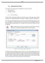
NOTE: The DF1 Slave mode only works with PLC5, SLC Typed Read and Write
messages as well as PLC2 Unprotected Read and Write messages.
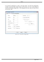
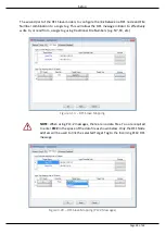
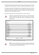
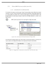
Figure 3.16. - DF1 Slave mode configuration
The DF1 Slave mode is configured in two steps. First, you must create a Target Name (CIP path
to the destination Logix controller) which will be used to link the DF1 File Number to the
destination Logix tag. When using PLC2 messages, the Target will be linked to the DF1 Node
Number. Therefore, if the device sending out PLC2 requests wants to access multiple Target
Tags, it will need to differentiate by using different Node Numbers.
Summary of Contents for PLX51-DF1-MSG
Page 1: ...PLX51 DF1 MSG DF1 Messenger DF1 to EtherNet IPTM Messenger December 2017 USER MANUAL...
Page 4: ...Page 4 of 69...
Page 10: ...Page 10 of 69...
Page 48: ...Operation Page 48 of 69...
Page 60: ...Page 60 of 69...
Page 64: ...Page 64 of 69...
Page 68: ...Page 68 of 69...


