MVI69E-MBS ♦ CompactLogix™ Platform
MVI69E-MBS Backplane Data Exchange
Modbus Serial Enhanced Communication Module
User Manual
ProSoft Technology, Inc.
Page 70 of 159
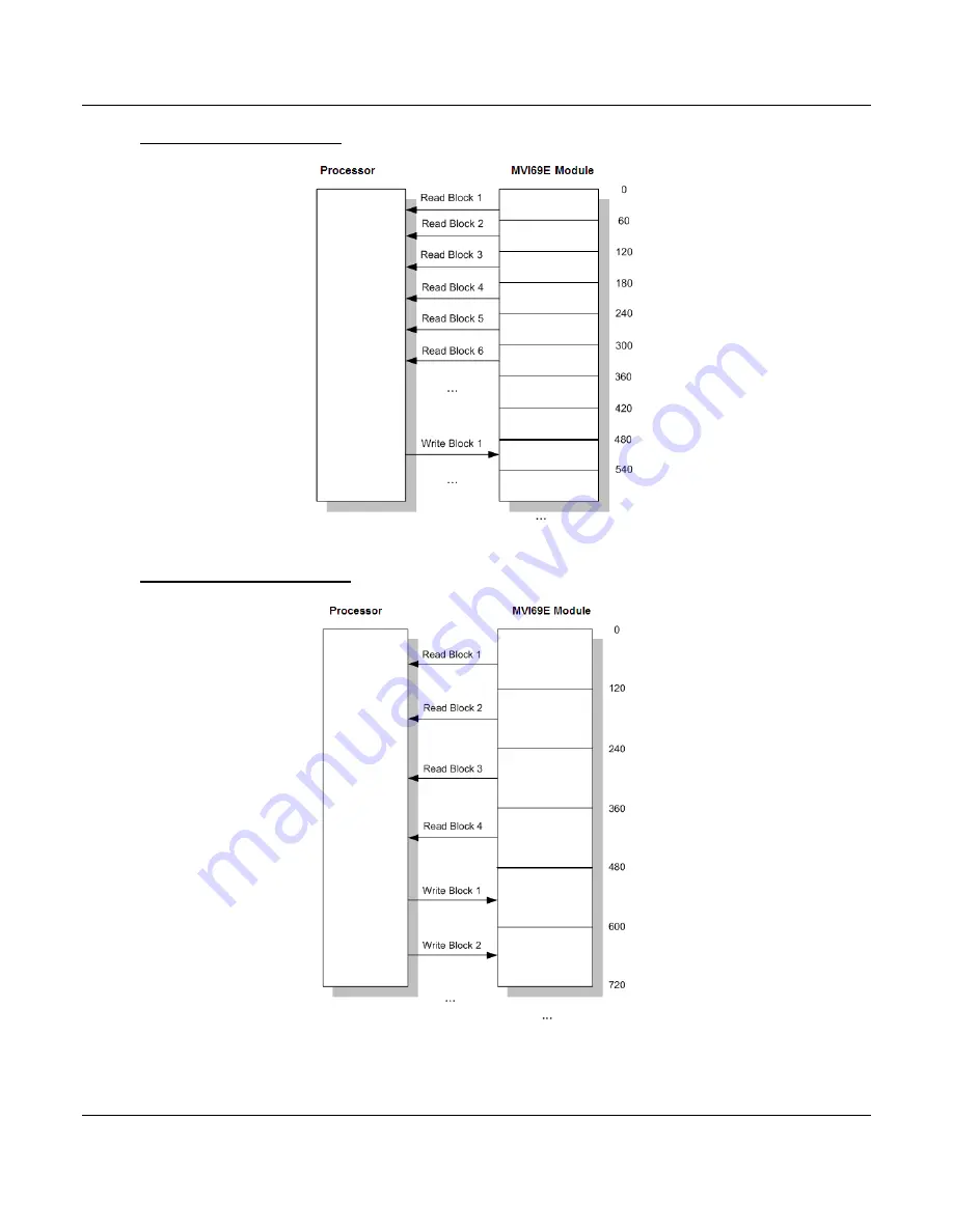
If Block Transfer Size = 60
If Block Transfer Size = 120
Page 1: ...MVI69E MBS CompactLogix Platform Modbus Serial Enhanced Communication Module August 11 2022 USER MANUAL ...
Page 2: ... or subsidiaries shall be responsible or liable for misuse of the information contained herein Information in this document including illustrations specifications and dimensions may contain technical inaccuracies or typographical errors ProSoft Technology makes no warranty or representation as to its accuracy and assumes no liability for and reserves the right to correct such inaccuracies or error...
Page 3: ...n in hazardous locations turn off power before replacing or wiring modules B Warning Explosion Hazard Do not disconnect equipment unless power has been switched off or the area is known to be non hazardous C These products are intended to be mounted in an ATEX IECEx Certified tool secured IP54 enclosure The devices shall provide external means to prevent the rated voltage being exceeded by transie...
Page 4: ...PCB 22 2 3 2 Creating and Exporting the L5X File 24 2 4 Importing the Add On Instruction 26 2 5 Adding Multiple Modules in the Rack Optional 29 2 5 1 Adding Another Module in PCB 29 2 5 2 Adding Another Module in Studio 5000 31 3 Configuring the MVI69E MBS Using PCB 36 3 1 Basic PCB Functions 36 3 1 1 Creating a New PCB Project and Exporting an L5X File 36 3 1 2 Renaming PCB Objects 36 3 1 3 Editi...
Page 5: ...69E MBS 88 6 4 Optional Add On Instruction 90 6 4 1 Setting Up the Optional AOI 92 6 4 2 Synchronizing the IP Settings from the MVI69E MBS to the Processor 94 6 4 3 Synchronizing the IP Settings from the Processor to the MVI69E MBS 95 6 4 4 Reading the Date Time from the MVI69E MBS to the Processor 96 6 4 5 Writing the Date Time from the Processor to the MVI69E MBS 97 7 Diagnostics and Troubleshoo...
Page 6: ... Slave Polling Enable Blocks 3001 3101 134 8 4 4 Slave Polling Status Blocks 3002 to 3006 3102 to 3106 135 8 4 5 Command Control Blocks 5001 to 5006 5101 to 5106 136 8 4 6 Add Event with Data Blocks 8000 8001 137 8 4 7 Get Event with Data Status Block 8100 138 8 4 8 Get Configuration File Information Block 9000 or 9000 139 8 4 9 Get Configuration File Block 9001 or 9001 140 8 4 10 Get General Modu...
Page 7: ...actLogix Platform Contents Modbus Serial Enhanced Communication Module User Manual ProSoft Technology Inc Page 7 of 159 9 Support Service Warranty 159 9 1 Contacting Technical Support 159 9 2 Warranty Information 159 ...
Page 8: ...power supply distance rating of 4 L43 and L45 installations on first 2 slots of 1769 bus It consumes 500 mA at 5 VDC Important For 1769 L23x processors please make note of the following limitation 1769 L23E QBFC1B 450 mA at 5 VDC No MVI69E module can be used with this processor The module requires 500 mA of available 5 VDC power Rockwell Automation Studio 5000 Logix Designer programming software R...
Page 9: ...ix or MicroLogix 1500 LRP processor How many words of data do you need to transfer in your application from CompactLogix or MicroLogix 1500 LRP to Module to CompactLogix or MicroLogix 1500 LRP from Module Is this module replacing an existing legacy MVI69 MCM module refer to section Legacy Mode on page 76 1 3 Package Contents The following components are included with your MVI69E MBS module and are...
Page 10: ...ition The following diagram describes the jumper settings Note Jumper pin placement on the circuit board may vary The Setup Jumper acts as write protection for the module s firmware In write protected mode the Setup pins are not connected and the module s firmware cannot be overwritten The module is shipped with the Setup jumper OFF If an update of the firmware is needed apply the Setup jumper to ...
Page 11: ...ation for each device to be connected to verify that suitable safety procedures are in place before installing or servicing the device After you verify the jumper placements insert the MVI69E MBS into the rack Use the same technique recommended by Rockwell Automation to remove and install CompactLogix or MicroLogix 1500 LRP modules Warning This module is not hot swappable Always remove power from ...
Page 12: ...ced Communication Module User Manual ProSoft Technology Inc Page 12 of 159 3 Push the module s bus lever back slightly to clear the positioning tab and move it firmly to the left until it clicks Ensure that it is locked firmly in place 4 Close all DIN rail latches ...
Page 13: ...orm Start Here Modbus Serial Enhanced Communication Module User Manual ProSoft Technology Inc Page 13 of 159 5 Press the DIN rail mounting area of the controller against the DIN rail The latches momentarily open and lock into place ...
Page 14: ... On Instruction to an Studio 5000 compatible file L5X file 4 Import the Add On Instruction the L5X file into Studio 5000 The L5X file contains the Add On Instruction user defined data types controller tags and ladder logic required to configure the MVI69E MBS module 2 1 Creating the Module in an Studio 5000 Project In an Studio 5000 project there are two ways you can add the MVI69E MBS module to t...
Page 15: ...n Profile Download the AOP file MVI69x_RevX X_AOP zip from the product webpage www prosoft technology com onto your local hard drive and then extract the files from the zip archive Make sure you have shut down Studio 5000 and RSLinx before you install the Add On Profile AOP 1 Run the MPSetup exe file to start the Setup Wizard Follow the Setup Wizard to install the AOP 2 Continue to follow the step...
Page 16: ...anual ProSoft Technology Inc Page 16 of 159 3 Click FINISH when complete The AOP is now installed in Studio 5000 You do not need to reboot the PC Using an Add On Profile 1 In Studio 5000 expand the I O CONFIGURATION folder in the Project tree Right click the appropriate communications bus and and then click NEW MODULE ...
Page 17: ... 17 of 159 This opens the Select Module Type dialog box In the Module Type Vendor Filters area uncheck all boxes except the PROSOFT TECHNOLOGY box A list of ProSoft Technology modules appears in the dialog box 2 Select the MVI69E MBS module in the list and click CREATE 3 A New Module dialog box opens Edit the NAME and SLOT for the module and click OK ...
Page 18: ...n Module Configuration Parameters page 39 A Block Transfer Size of 60 uses an I O TABLE SIZE of 62 61 words A Block Transfer Size of 120 uses an I O TABLE SIZE of 122 121 words A Block Transfer Size of 240 uses an I O TABLE SIZE of 242 241 words Applications that require smaller amounts of data or faster update times such as ControlNet networks will benefit from smaller block transfer sizes The MV...
Page 19: ...t Using a Generic 1769 Module Profile This procedure is not required if you installed the ProSoft Technology Add On Profile for this module 1 Expand the I O CONFIGURATION folder in the Project tree Right click the appropriate communications bus and choose NEW MODULE This opens the Select Module Type dialog box 2 In the Select Module Type dialog select the 1769 MODULE and click on the CREATE button...
Page 20: ... Modbus communications Comm Format Select DATA INT Slot Enter the slot number in the rack where the MV69E MBS module is installed Input Assembly Instance 101 Input Size 62 122 242 Output Assembly Instance 100 Output Size 61 121 241 Configuration Assembly Instance 102 Configuration Size 0 The following illustration shows an example where the module was configured for a block transfer size of 60 wor...
Page 21: ...figuration Builder PCB on our web site www prosoft technology com The installation filename contains the PCB version number For example PCB_4 3 4 5 0238 EXE Installing PCB from the ProSoft website 1 Open a browser window and navigate to www prosoft technology com 2 Navigate to the ProSoft Configuration Builder download link and save the file to your Windows desktop 3 After the download completes d...
Page 22: ...ration project in ProSoft Configuration Builder PCB and to export the L5X file for the project 2 3 1 Setting Up the Project in PCB 1 Start PROSOFT CONFIGURATION BUILDER PCB 2 The PCB window consists of a tree view on the left and an information pane and a configuration pane on the right side of the window The tree view consists of folders for Default Project and Default Location with a Default Mod...
Page 23: ...iew right click DEFAULT MODULE and then click CHOOSE MODULE TYPE This opens the Choose Module Type dialog box 4 In the Product Line Filter area of the dialog box click MVI69 In the Select Module Type dropdown list click MVI69E MBS and then click OK to save your settings and return to the ProSoft Configuration Builder window The MVI69E MBS icon is now visible in the tree view ...
Page 24: ...t is exported Before exporting the L5X file to the PC Laptop check the Block Transfer Size and Slot Number parameters 1 Expand the MVI69E MBS icon by clicking the symbol beside it Similarly expand the icon Double click the icon to open the Edit Module dialog box 2 Set the Block Transfer Size to the desired size of the data blocks transferred between the module and processor 60 120 or 240 words Blo...
Page 25: ...f 159 3 Edit the Slot Number indicating where the module is placed in the 1769 bus 4 Click OK to close the Edit Module dialog box The L5X file is now ready to be exported to the PC Laptop 5 Right click the MVI69E MBS icon in the project tree and choose EXPORT AOI FILE 6 Save the L5X file to the PC Laptop in an easily found location such as Windows Desktop ...
Page 26: ...nd the MAINTASK folder 3 Expand the MAINPROGRAM folder The MAINROUTINE contains rungs of logic The very last rung in this routine is blank This is where you can import the Add On Instruction Note You can place the Add On Instruction in a different routine than the MainRoutine Make sure to add a rung with a jump instruction JSR in the MainRoutine to jump to the routine containing the Add On Instruc...
Page 27: ...159 5 Select the L5X file that you exported from PCB Creating and Exporting the L5X File page 24 This opens the Import Configuration dialog box Click TAGS under MAINROUTINE to display the controller tags in the Add On Instruction Note If you are using RSLogix version 16 or earlier the Import Configuration dialog box does not contain the Import Content tree ...
Page 28: ...NAME column NAME column for RSLogix version 16 or less For example if your module is located in slot 3 change Local 1 I in the FINAL NAME column to Local 3 I Do the same for Local 1 O Note If your module is located in Slot 1 of the local rack this step is not required 7 Click OK to confirm the import 8 When the import is completed the new rung with the Add On Instruction is visible The procedure a...
Page 29: ...r PCB project 2 Export the module configuration as an L5X file 3 Add a new MVI69E MBS to the Studio 5000 project 4 Import the L5X file into Studio 5000 for the new module as an Add On Instruction 2 5 1 Adding Another Module in PCB 1 Start ProSoft Configuration Builder 2 Right click DEFAULT LOCATION which you can rename and choose ADD MODULE 3 Right click NEW MODULE and choose CHOOSE MODULE TYPE 4 ...
Page 30: ...me The default name on a duplicate module appends a number to the end such as MVI69E MBS_000 MVI69E MBS_001 etc 6 You can rename the module by right clicking the module and choosing Rename 7 Configure the module parameters See Module Configuration Parameters page 39 and then export the AOI L5X file for the new module right click the module and choose EXPORT AOI FILE See Creating and Exporting the ...
Page 31: ...e 8 Adding an additional module to the rack is similar to installing a new module however the name of the module must be unique 1 Start Studio 5000 and open the project 2 In Studio 5000 locate the I O CONFIGURATION folder Right click COMPACTBUS LOCAL and choose NEW MODULE 3 In the Select Module Type dialog box select the MVI69E MBS module o If you are using an Add On Profile AOP this adds the MVI6...
Page 32: ... The New Module dialog box appears Enter a unique name for the new module and confirm the slot number of the new module 5 Click OK The new module is now visible 6 You must also import the Add On Instruction AOI for the new module see Adding another module in PCB page 29 In the Controller Organizer pane double click MAINROUTINE to open the ladder for the routine ...
Page 33: ...unication Module User Manual ProSoft Technology Inc Page 33 of 159 7 Right click an empty rung in the routine and then choose IMPORT RUNGS 8 Select the L5X file you created and exported for the new module and click IMPORT The new L5X file has a unique filename that is specific to the new module ...
Page 34: ...s for the second module to make them unique 10 Associate the I O connection variables to the correct module in the corresponding slot number The default values are Local 1 I and Local 1 O You must edit these values if the card is placed in a slot location other than slot 1 Local 1 x means the card is located in slot 1 Since the second card is placed in slot 2 change the FINAL NAME to Local 2 I and...
Page 35: ...odule in RSLogix Modbus Serial Enhanced Communication Module User Manual ProSoft Technology Inc Page 35 of 159 11 Click OK The setup procedure is now complete Save the project It is ready to download to the CompactLogix or MicroLogix 1500 LRP processor ...
Page 36: ... When the MVI69E MBS module boots up it requests the processor to send the configuration over the backplane in special Configuration Blocks See the chapter Adding the Module to RSLogix page 14 for the procedures to create a new PCB project and export a L5X file for the processor This chapter describes the module configuration parameters in detail as well as how to download the configuration to the...
Page 37: ...e sign next to any icon to view module information and configuration options 3 Double click any icon to open an Edit dialog box To edit a parameter select the parameter in the left pane and make your changes in the right pane Note Depending on the parameter you must enter text or a valid number or select from a list of options 4 Click OK to save your changes 5 Double click any icon to open an Edit...
Page 38: ...ADD ROW 7 To edit the row click EDIT ROW This opens an Edit dialog box 3 1 4 Printing a Configuration File 1 In the main PCB window right click the MVI69E MBS icon and then choose VIEW CONFIGURATION 2 In the View Configuration dialog box click the FILE menu and then click PRINT 3 In the Print dialog box choose the printer to use from the drop down list select the printing options and then click OK...
Page 39: ... before communications are halted Error Status Block Pointer 1 to 9939 Starting register location in the module s database for the error status table If a value of 1 is entered the error status data is not placed in the database This data must be placed in the read data range of module memory This data includes the module version information and all server error status data Refer to MBS STATUS pag...
Page 40: ... of data bits Stop Bits 1 or 2 Sets the number of stop bits that signal the end of a character in the data stream For most applications use one stop bit For slower devices that require more time to re synchronize use two stop bits All devices communicating through this port must use the same number of stop bits RTS On 0 to 65535 milliseconds Sets the number of milliseconds to delay after Ready To ...
Page 41: ...or if you do not plan to use floating point data in your application then set this parameter to NO which is the default setting You also need to set the Float Start and Float Offset parameters to appropriate values whenever the Float Flag parameter is set to YES Float Start 0 to 9998 Defines the first register of floating point data All requests with register values greater than or equal to this v...
Page 42: ...affect retries of a command as retries are issued when a command failure is recognized Error Delay Counter 0 to 60000 Specifies the number of poll attempts to be skipped before trying to re establish communications with a slave that has failed to respond to a command within the time limit set by the Response Timeout parameter After the slave fails to respond the master skips sending commands that ...
Page 43: ...k Bit Input Offset 0 to 9999 Specifies the offset address into the internal Modbus database for network requests for Modbus function 2 commands For example if you set the value to 150 an address request of 0 returns the value at register 150 in the database Word Input Offset 0 to 9998 Specifies the offset address into the internal Modbus database for network requests for Modbus function 4 commands...
Page 44: ...or write the data area in the device to interface with and the registers in the internal database to be associated with the device data The Master command list supports up to 250 commands The command list is processed from top Command 0 to bottom Read commands are executed without condition You can set write commands to execute only if the data in the write command changes Conditional Enable If th...
Page 45: ...level or register level address with an allowable range of 0 to 9999 For Modbus functions 1 2 5 and 15 this parameter is interpreted as a bit level address with an allowable range of 0 to 159 999 Note This bit address range is available with ProSoft Configuration Builder PCB v4 6 or later Previous versions have a range of 0 to 65535 If the command is a read function the data read from the slave de...
Page 46: ...s made in the byte ordering ABCD ABCD Word Swap 1 The words are swapped ABCD CDAB Word and Byte Swap 2 The words are swapped then the bytes in each word are swapped ABCD DCBA Byte Swap 3 The bytes in each word are swapped ABCD BADC Note Each pair of characters is a byte Ex AB and CD Two pairs of characters is 16 bit register Ex ABCD Node Address 1 to 255 0 broadcast Specifies the Modbus slave node...
Page 47: ...us addresses 0x 1x 3x 4x Override Value Upon Error This parameter is only applicable for Enable Codes 3 Bit Word Override or 4 Float Override If an error occurs associated to a read command the module automatically populates the associated database area with this override value 3 2 4 Ethernet 1 This section defines the permanent IP address Subnet Mask and Gateway of the module In the ProSoft Confi...
Page 48: ...munication Module User Manual ProSoft Technology Inc Page 48 of 159 3 3 Downloading the Configuration File to the Processor 1 In the ProSoft Configuration Builder tree view right click the module icon and choose DOWNLOAD FROM PC TO DEVICE 2 In the Download Configuration File dialog box click RSWHO ...
Page 49: ...ual ProSoft Technology Inc Page 49 of 159 3 Browse to and then highlight the CompactLogix or MicroLogix 1500 LRP processor and click OK 4 Notice the CIPConnect path has been updated in the Download Configuration File dialog box Click TEST CONNECTION to verify the path is active and can successfully connect to the processor ...
Page 50: ...Technology Inc Page 50 of 159 5 When ready click DOWNLOAD to download the configuration file to the processor Following the download process the module is automatically rebooted 6 After rebooting the ladder logic sends the configuration data from the processor to the module When that is complete the module starts Modbus communications ...
Page 51: ...CB Modbus Serial Enhanced Communication Module User Manual ProSoft Technology Inc Page 51 of 159 3 4 Uploading the Configuration File from the Processor 1 In the ProSoft Configuration Builder tree view right click the MVI69E MBS icon and choose UPLOAD FROM DEVICE TO PC ...
Page 52: ... Manual ProSoft Technology Inc Page 52 of 159 2 In the Upload Configuration File dialog box the CIPConnect path should already be constructed if you have previously downloaded the configuration file from the same PC If not click RSWHO browse to then select the CompactLogix or MicroLogix 1500 LRP Processor and click OK ...
Page 53: ...anced Communication Module User Manual ProSoft Technology Inc Page 53 of 159 3 Click TEST CONNECTION to verify the path is active and can successfully connect to the processor 4 When ready click UPLOAD When upload is complete click CLOSE 5 PCB now displays the uploaded configuration file ...
Page 54: ...contain any combination of Individual controller tags Controller tag arrays Lower level controller tag structures The controller tags are included in the MVI69E MBS Add On Instruction ladder logic After you import the Add On Instruction you can find the controller tags in the Controller Tags subfolder located in the Controller folder in the Controller Organizer pane of the main Studio 5000 window ...
Page 55: ...ller tag structure you see that it contains two controller tag arrays MBS DATA ReadData and MBS DATA WriteData which are 600 element integer arrays by default The controller tags in the Add On Instruction are commented in the DESCRIPTION column Notice that the DATA TYPE column displays the data types used to declare each controller tag controller tag array or controller tag structure Individual co...
Page 56: ...MBS module has pre defined UDTs You can find them in the User Defined subfolder located in the Data Types folder in the Controller Organizer pane of the main RSLogix window Like the controller tags the UDTs are organized in a multiple level tree structure 4 2 1 MVI69E MBS User Defined Data Types Twenty different UDTs are defined for the MVI69E MBS Add On Instruction The main UDT MBSMODULEDEF conta...
Page 57: ...data types used to declare the MBS DATA ReadData and MBS DATA WriteData controller tag arrays The UDTs are commented in the DESCRIPTION column Tip If more than 600 words of Read or Write Data are needed the MBS DATA ReadData and MBS DATA WriteData controller tag arrays can be expanded Simply edit the size of the ReadData or WriteData integer array in the DATA TYPE column of the MBSDATA UDT In the ...
Page 58: ...ce PCB calculates a unique CRC to protect data integrity Any change to the configuration parameters directly in this array will not match the calculated CRC Tag Name Description MBS CONFIG FileData This parameter contains the MBS configuration data after it has been downloaded from PCB It is displayed in ASCII format Note MBS configuration changes cannot be made directly in this array the configur...
Page 59: ...Disable 0 Enable 1 MBS CONTROL PortControl Portx CmdEnableBits x 0 or 1 Index of command to be controlled Example Command 20 in port 1 command list can be controlled at CmdEnableBits 1 3 This is the 20th bit offset MBS CONTROL CmdControl This array allows the processor to dynamically enable configured commands for execution Tag Name Range Description MBS CONTROL CmdControl CmdControlTrigger 0 or 1...
Page 60: ...be associated with command Control function MBS CONTROL EventCmd_DB Data SlaveID 1 to 248 Slave ID of Modbus slave MBS CONTROL EventCmd_DB Data InternalDBAddress 0 to 9999 Used only if UseModuleDBAddress 1 MVI69E database address word address for functions 3 4 6 16 and bit address for 1 2 5 15 MBS CONTROL EventCmd_DB Data PointCount 0 to 125 Number of bit words associated with this command MBS CON...
Page 61: ...ortNumber 1 or 2 Port number to be associated with command MBS CONTROL EventCmd_Processor Data SlaveAddress 1 to 248 Slave ID of Modbus slave MBS CONTROL EventCmd_Processor Data ModbusFunctionCode Modbus function code 5 6 15 or 16 MBS CONTROL EventCmd_Processor Data DeviceDBAddress 0 to 9999 Modbus address of the target slave database MBS CONTROL EventCmd_Processor Data PointCount 0 to 125 Number ...
Page 62: ...IDs 2 4 A value of 3 would be entered in the MBS CONTROL SlavePoll Portx EnableSlaveCount tag since there are 3 slave ID s to enable Note The AOI will not reset the tag array to 0 after being enabled MBS CONTROL SlavePoll Portx DisableSlaves 0 or 1 Triggers disable slaves request 0 Disable 1 Enable Note The AOI resets the tag to 0 after being enabled MBS CONTROL SlavePoll Portx DisableSlaveCount 1...
Page 63: ...99 Millisecond MBS CONTROL GetStatus This tag allows the processor to retrieve status from the module Tag Name Range Description GetStatus 0 or 1 Triggers status retrieval from the module 0 Disable 1 Enable MBS CONTROL ResetStatus This tag allows the processor to reset the module status counters Tag Name Range Description ResetStatus 0 or 1 Triggers module status counter reset 0 Disable 1 Enable M...
Page 64: ...n the port MBS STATUS PortxStats PortErrSent Total number of message errors sent out of the port MBS STATUS PortxStats PortErrRec Total number of message errors received on the port MBS STATUS PortxStats CurrErr Not used MBS STATUS PortxStats LastErr Not used MBS STATUS Block Backplane transfer status MBS STATUS Block Read Total number of read blocks transferred from the module to the processor MB...
Page 65: ...ConfigFile WordLength Length of configuration data to be included in block transfer MBS UTIL ConfigFile BlockCount Not used MBS UTIL ConfigFile FileOffset Offset in configuration file to use as a starting point for copying over configuration data MBS UTIL ConnectionInputSize Holds size of the Connection Input array MBS UTIL BlockTransferSize Size of the backplane transfer blocks MBS UTIL SlotNumbe...
Page 66: ...ipt The following topics describe several concepts that are important for understanding the operation of the MVI69E MBS module This is the order of operations on power up 1 The module begins the following logical functions o Initialize hardware components o Initialize CompactLogix or MicroLogix 1500 LRP backplane driver o Test and clear all RAM 2 Read configuration from the CompactLogix or MicroLo...
Page 67: ... send to the processor Data in the input image is placed in the Controller Tags in the processor by the ladder logic The input image for the module may be set to 62 122 or 242 words depending on the block transfer size parameter set in the configuration file This data area permits fast throughput of data between the module and the processor Applications that require smaller amounts of data or fast...
Page 68: ...uest from the Processor to the Module These blocks of data transfer information from the processor to the module The structure of the output image used to transfer this data is shown below Offset Description Length words 0 Write Block ID 1 1 to n Write Data n n 60 120 or 240 depending on the Block Transfer Size parameter refer to the configuration file The Write Block ID is an index value that det...
Page 69: ...cation uses three read and two write blocks the sequence is as follows R1W1 R2W2 R3W1 R1W2 R2W1 R3W2 R1W1 This sequence continues until interrupted by other write block numbers sent by the controller or by a command request from a node on the Modbus network or operator control through the module s Configuration Debug port The following example shows a typical backplane communication application If...
Page 70: ... MBS CompactLogix Platform MVI69E MBS Backplane Data Exchange Modbus Serial Enhanced Communication Module User Manual ProSoft Technology Inc Page 70 of 159 If Block Transfer Size 60 If Block Transfer Size 120 ...
Page 71: ...MVI69E MBS CompactLogix Platform MVI69E MBS Backplane Data Exchange Modbus Serial Enhanced Communication Module User Manual ProSoft Technology Inc Page 71 of 159 If Block Transfer Size 240 ...
Page 72: ...structions to offset data stored in the database to addresses different from addresses requested in the received messages 2 A Modbus Master device such as a Modicon PLC or an HMI application issues a read or write command to the module s node address The port driver qualifies the message before accepting it into the module Rejected commands cause an Exception Response 3 After the module accepts th...
Page 73: ...message c In Pass Through mode if the Slave Driver receives a write request it does not send the data directly to the module s internal database It puts the data to be written into a special Input Image with a special Block ID code to identify it as a Pass Through Write Block and substitutes this special block in place of the next regular Read Data Block The special block is processed by the ladde...
Page 74: ...nto and out of the module Step Description 1 Upon module boot up the Master driver obtains configuration data from the MBS controller tags The configuration data retrieved includes port configuration and the Master Command List Special Commands can be issued directly from the CompactLogix or MicroLogix 1500 LRP processor using Event Commands and Command Control These command values are used by the...
Page 75: ...up to 2000 bits for Function Codes 1 2 or 15 Note 125 words is the maximum count allowed by the Modbus protocol Some field devices may support less than the full 125 words Check with the device manufacturer for the maximum count supported by the particular slave device Slave node address Modbus Function Code This is the type of command that is issued Source or destination address in the slave devi...
Page 76: ...e is backward compatible with the MVI69 MCM You may replace an existing MVI69 MCM with the MVI69E MBS module Legacy Mode without any changes to the existing CompactLogix ladder logic application You may also convert the existing MVI69 MCM PCB configuration to the MVI69E MBS module in Legacy Mode This conversion procedure is supported by PCB v4 4 24 20 0302 or later 6 1 Webpage Configuration 1 Open...
Page 77: ...de Modbus Serial Enhanced Communication Module User Manual ProSoft Technology Inc Page 77 of 159 3 In the Advanced Settings page change the LEGACY MODE field to Yes then click on the UPDATE LEGACY MODE button 4 Confirm the update by clicking OK ...
Page 78: ...ix Platform Legacy Mode Modbus Serial Enhanced Communication Module User Manual ProSoft Technology Inc Page 78 of 159 5 The module will reboot during the update process 6 Once complete the homepage displays Legacy Mode Yes ...
Page 79: ...chnology Inc Page 79 of 159 6 2 PCB Configuration You will need to convert the existing MVI69 MCM PCB project to an MVI69E MBS project 1 Open the existing MVI69 MCM project in PCB 2 Right click on the MVI69 MCM icon and select CONVERT TO ENHANCED MODE 3 After the conversion the PCB module parameters are updated ...
Page 80: ... Modbus Serial Enhanced Communication Module User Manual ProSoft Technology Inc Page 80 of 159 6 2 1 Comment Parameter Under the MODULE COMMENT option in the module configuration you can make a note that this configuration is a Legacy conversion ...
Page 81: ...umber of consecutive backplane transfer failures that can occur before communications are halted Error Status Block Pointer 1 to 5000 Starting register location in the module s database for the error status table If a value of 1 is entered the error status data is not placed in the database This data must be placed in the Read Data Range of module memory This data includes the module version infor...
Page 82: ...rotocol All devices communicating through this port must use the same number of data bits Stop Bits 1 or 2 Sets the number of stop bits that signal the end of a character in the data stream For most applications use one stop bit For slower devices that require more time to re synchronize use two stop bits All devices communicating through this port must use the same number of stop bits RTS On 0 to...
Page 83: ... Count 0 to 60000 Master mode Specifies the number of poll attempts to be skipped before trying to re establish communications with a slave that has failed to respond to a command within the time limit set by the Response Timeout parameter After the slave fails to respond the master skips sending commands that should have been sent to the slave until the number of skipped commands matches the valu...
Page 84: ...n the device to interface with and the registers in the internal database to be associated with the device data The Master command list supports up to 100 commands The command list is processed from top Command 0 to bottom Read commands are executed without condition You can set write commands to execute only if the data in the write command changes Conditional Enable If the register data values i...
Page 85: ...e section Note When using a bit level command you must define this field at the bit level For example when using function codes 1 or 2 for a Read command you must have a enter of 160 to place the data in the MBS DATA ReadData 10 controller tag in Studio 5000 Think of it as the 160th bit of MBS internal memory MBS Internal register 10 16 bits per register 160 Use this formula for function codes 5 o...
Page 86: ...ue to zero the command is a broadcast message on the network The Modbus protocol permits broadcast commands for write operations Do not use this node address for read operations Modbus Function 1 2 3 4 5 6 15 16 Specifies the Modbus function to be executed by the command These function codes are defined in the Modbus protocol 1 Read Coil Status 0xxxx 2 Read Input Status 1xxxx 3 Read Holding Regist...
Page 87: ...orm Legacy Mode Modbus Serial Enhanced Communication Module User Manual ProSoft Technology Inc Page 87 of 159 6 2 5 Ethernet 1 Parameter The ETHERNET 1 option allows you to configure the module s IP Address Subnet Mask and Gateway ...
Page 88: ...logy Inc Page 88 of 159 6 3 Downloading PCB Configuration to the MVI69E MBS 1 Right click on the MVI69 MBS icon and select DOWNLOAD FROM PC TO DEVICE 2 In the Download files from PC to module dialog click on the BROWSE DEVICE S button The ProSoft Discovery Service Utility searches for ProSoft devices on the network ...
Page 89: ...ced Communication Module User Manual ProSoft Technology Inc Page 89 of 159 3 Double click on the module icon 4 Click DOWNLOAD When complete the Module Running message is displayed 5 Once complete the MVI69E MBS in Legacy Mode will operate similarly to the MVI69 MCM ...
Page 90: ...troller tags the Optional AOI allows you to request and set the module s IP address date and time These optional features are not supported by the MVI69E MCM legacy module Note The Optional AOI may be added to an existing legacy MVI69E MBS application to add the new functionality during a module replacement 1 Add a new rung to the existing processor ladder logic Right click on the new rung and sel...
Page 91: ...egacy Mode Modbus Serial Enhanced Communication Module User Manual ProSoft Technology Inc Page 91 of 159 3 At the Import Configuration window select the Operation parameter to CREATE Then click OK 4 The imported AOI rung is now in place ...
Page 92: ...logy Inc Page 92 of 159 6 4 1 Setting Up the Optional AOI 1 Click on the ReadEthernetMSG icon to configure the message route 2 In the Message Configuration dialog under the Communication tab select the BROWSE button 3 In the Message Path Browser dialog select the MVI69E MBS module under the 1769 Bus and click at OK ...
Page 93: ...nication Module User Manual ProSoft Technology Inc Page 93 of 159 4 The module name is displayed in the Path field Click OK to confirm the route configuration 5 Repeat the same procedure to set the route for the remaining messages WriteEthernetMSG ReadClockMSG WriteClockMSG ...
Page 94: ...e MVI69E MBS to the Processor This section covers the process to read the IP settings from the MVI69E MBS and implement them in the processor 1 To trigger the IP settings read operation set the MVI69EMBSEthernet Read bit to 1 Once the operation is concluded the tag will automatically reset to 0 2 The data is stored in the MVI69EMBSEthernet Config tags IP Netmask Gateway as follows ...
Page 95: ... from the Processor to the MVI69E MBS This section covers the process to send the IP settings from the processor to the MVI69E MBS 1 Populate the IP settings in the MVI69EMBSEthernet Config tag 2 Set the MVI69EMBSEthernet Write bit to 1 to trigger the IP settings write operation 3 The MVI69EMBSEthernet Write bit will automatically reset to 0 once the operation is concluded ...
Page 96: ... of 159 6 4 4 Reading the Date Time from the MVI69E MBS to the Processor 1 Toggle the MVI69EMBSClock Read bit to 1 to toggle the date time read operation 2 The MVI69EMBSClock Read bit will automatically reset to 0 once the operation is concluded 3 The date and time read from the MVI69E MBS is stored at the MVI69EMBSClock Config tag ...
Page 97: ...MVI69E MBS 1 Populate date and time values in the MVI69EMBSClock Config tag 2 Toggle the MVI69EMBSClock Write bit to 1 to trigger the write date time operation 3 The MVI69EMBSClock Write tag will be automatically reset to 0 once the write date time operation is concluded For further information concerning the MVI69 MCM please download the MVI69 MCM User Manual from www prosoft technology com ...
Page 98: ...perating status LED Status Indication ETH On Ethernet communications are ok Off No Ethernet cable connected P1 Green Data is being transferred between the module and the Modbus network on Port 1 Red Communication error detected Off No Modbus network activity detected P2 Green Data is being transferred between the module and the Modbus network on Port 2 Red Communication error detected Off No Modbu...
Page 99: ...munication to be possible 7 3 Clearing a Fault Condition Typically if the OK LED on the front of the module remains RED for more than ten seconds a hardware problem has been detected or the program has exited To clear the condition follow these steps 1 Turn off power to the rack 2 Remove the card from the rack 3 Verify that all jumpers are set correctly 4 If the module requires a Compact Flash car...
Page 100: ...Verify that all modules in the rack are correctly configured Module Errors Problem description Steps to take BP ACT LED not present on MVI56E modules remains OFF or blinks slowly MVI69 modules with scrolling LED display Backplane Status condition reads ERR This indicates that backplane transfer operations are failing Connect to the module s Configuration Debug port to check this To establish backp...
Page 101: ...ogy Inc Page 101 of 159 7 5 Connecting the PC to the Module s Ethernet Port With the module securely mounted connect one end of the Ethernet cable to the ETH1 Port and the other end to an Ethernet hub or switch accessible from the same network as the PC Or connect directly from the Ethernet Port on the PC to the ETH 1 Port on the module ...
Page 102: ...ice is unable to locate the modules To use ProSoft Configuration Builder arrange the Ethernet connection so that there is no router layer 3 switch between the computer and the module OR reconfigure the router layer 3 switch to allow routing of the UDP broadcast messages 1 In the tree view in ProSoft Configuration Builder PCB select the MVI69E MBS module For instructions on opening and using a proj...
Page 103: ... Choose an unused IP within your subnet and then click OK Important The temporary IP address is only valid until the next time the module is initialized For information on how to set the module s permanent IP address see Ethernet 1 page 47 6 Close the ProSoft Discovery Service window Enter the temporary IP address in the ETHERNET ADDRESS field of the Connection Setup dialog box then click TEST CON...
Page 104: ...nostic menus for debugging and troubleshooting To connect to the module s Configuration Debug Ethernet port 1 In the tree view in ProSoft Configuration Builder right click the MVI69E MBS module and then choose DIAGNOSTICS For instructions on opening and using a project in PCB please refer to Configuring the MVI69E MBS Using PCB page 36 2 After the Diagnostics window opens click the SET UP CONNECTI...
Page 105: ...chnology Inc Page 105 of 159 3 In the Ethernet field of the Connection Setup dialog box enter the current IP address whether it is temporary or permanent Click TEST CONNECTION to verify that the module is accessible with the current settings 4 If the TEST CONNECTION is successful click CONNECT The Diagnostics window is now visible ...
Page 106: ...Menu In the Diagnostics window in ProSoft Configuration Builder the Diagnostics menu is available through the Ethernet configuration port The menu is arranged as a tree structure 7 6 2 Monitoring Network Configuration Information In the Diagnostics window in Prosoft Configuration Builder click NETWORK and then click CONFIG to view the Ethernet network configuration information ...
Page 107: ...l Enhanced Communication Module User Manual ProSoft Technology Inc Page 107 of 159 7 6 3 Monitoring Backplane Information In the Diagnostics window in ProSoft Configuration Builder click BACKPLANE to view the backplane information This menu has two submenus CONFIGURATION STATUS ...
Page 108: ...The MODBUS PORT 1 and MODBUS PORT 2 menus include the following submenus Configuration Status General status for the port Master Commands Used when port is configured as a Modbus master Slave Status List Status of each slave on the network used when port is configured as a Modbus master Master Command Status Status code for each master command used when port is configured as a Modbus master ...
Page 109: ...l ProSoft Technology Inc Page 109 of 159 7 6 5 Monitoring Data Values in the Module s Database In the Diagnostics window in ProSoft Configuration Builder click DATABASE and then click DECIMAL to view the contents of the MVI69E MBS module s internal database You can view data values in ASCII Hexadecimal and Float format ...
Page 110: ...n 1 Illegal Function Code 2 Illegal Data Address 3 Illegal Data Value 4 Failure in Associated Device 5 Acknowledge 6 Busy Rejected Message 7 7 2 Module Communication Error Codes Code Description 1 CTS modem control line not set before transmit 2 Timeout while transmitting message 11 Timeout waiting for response after request 253 Incorrect slave address in response 254 Incorrect function code in re...
Page 111: ... well as the ability to set the date and time reboot the module and download firmware upgrade to the module Enter the assigned IP address of the module into a web browser or use the following steps in PCB 1 In the PCB Diagnostics window click the SET UP CONNECTION button 2 In the Connection Setup dialog box click BROWSE DEVICE S to start ProSoft Discovery Service 3 Right click the module icon and ...
Page 112: ... transfer between processor and module Ladder Logic is used for data transfer between module and processor Sample Add On Instruction file included Configuration data obtained from and stored in the processor Supports CompactLogix or MicroLogix 1500 LRP processors with 1769 I O bus capability and at least 500 mA of 5 VDC backplane current available 8 1 1 Hardware Specifications Specification Descri...
Page 113: ...7 Report Slave ID Slave Only 22 Mask Write Holding Register Slave Only 23 Read Write Holding Registers Slave Only 8 2 About the Modbus Protocol Modbus is a widely used protocol originally developed by Modicon in 1978 Since that time the protocol has been adopted as a standard throughout the automation industry The original Modbus specification uses a serial connection to communicate commands and d...
Page 114: ...ter to interact with all data contained in the module This data can be derived from other Modbus slave devices on the network through a Master port or from the CompactLogix or MicroLogix 1500 LRP processor Parameter Description Node address 1 to 247 software selectable Status Data Error codes counters and port status available per configured slave port 8 2 3 Function Codes Supported by the Module ...
Page 115: ... Node Address Function Code Data Start Point High Data Start Point Low Number of Points High Number of Points Low Error Check Field 2 bytes 0B 01 00 13 00 25 CRC Response An example response to Read Coil Status is as shown in the table below The data is packed one bit for each coil The response includes the slave address function code quantity of data characters the data characters and error check...
Page 116: ...1100 1101 Binary Reading from left to right this shows that coils 27 26 23 22 and 20 are all on The other Data Coil Status bytes are decoded similarly Due to the quantity of coil statuses requested the last data field which is shown 1B HEX 0001 1011 Binary contains the status of only 5 coils 52 to 56 instead of 8 coils The 3 left most bits are provided as zeros to fill the 8 bit format ...
Page 117: ...ints Low Error Check Field 2 bytes 0B 02 00 C4 00 16 CRC Response An example response to Read Input Status is as shown in the table below The data is packed one bit for each input The response includes the slave address function code quantity of data characters the data characters and error checking Data is packed with one bit for each input 1 ON 0 OFF The lower order bit of the first character co...
Page 118: ...eing sent out to the Modbus network The byte values below are in hexadecimal display Node Address Function Code Data Start Registers High Data Start Registers Low Data Number of Registers High Data Number of Registers Low Error Check Field 2 bytes 0B 03 00 6B 00 03 CRC Response The addressed slave responds with its address and the function code followed by the information field The information fie...
Page 119: ...ress Function Code Data Start Point High Data Start Point Low Data Number of Points High Data Number of Points Low Error Check Field 2 bytes 0B 04 00 08 00 01 CRC Response The addressed slave responds with its address and the function code followed by the information field The information field contains 1 byte describing the quantity of data bytes to be returned The contents of the registers reque...
Page 120: ...he Modbus network The byte values below are in hexadecimal display Node Address Function Code Data Start Bit High Data Start Bit Low Number of Bits High Number of Bits Low Error Check Field 2 bytes 0B 05 00 AC FF 00 CRC Response The normal response to the Command Request is to re transmit the message as received after the coil state has been altered Node Address Function Code Data Coil Bit High Da...
Page 121: ...11 Node Address Function Code Data Start Bit High Data Start Bit Low Preset Data Register High Preset Data Register Low Error Check Field 2 bytes 0B 06 00 01 00 03 CRC Response The response to a preset single register request is to re transmit the query message after the register has been altered Node Address Function Code Data Register High Data Register Low Preset Data Register High Preset Data ...
Page 122: ...ted Only Sub function 00 is supported by the MVI69E MBS module 00 Return Query Data The data passed in the request data field is to be returned looped back in the response The entire response message should be identical to the request Sub function Data Field Request Data Field Response 00 00 Any Echo Request Data Example and State Diagram Here is an example of a request to remote device to Return ...
Page 123: ...Reference Modbus Serial Enhanced Communication Module User Manual ProSoft Technology Inc Page 123 of 159 The data fields in responses to other kinds of queries could contain error counts or other data requested by the sub function code ...
Page 124: ...example forces 10 coils starting at address 20 13 HEX The two data fields CD 1100 and 00 0000 000 indicate that coils 27 26 23 22 and 20 are to be forced on Note This is the structure of the message being sent out to the Modbus network The byte values below are in hexadecimal display Node Address Func Code Coil Address High Coil Address Low Number of Coils High Number of Coils Low Byte Count Force...
Page 125: ...le below is a request to write 2 registers starting at register 40002 in slave 11 Note This is the structure of the message being sent out to the Modbus network The byte values below are in hexadecimal display Node Address Func Code Data Start Address High Data Start Address Low Number of Points High Number of Points Low Byte Count Data High Data Low Data High Data Low Error Check Field 2 bytes 0B...
Page 126: ...er tags with different data types that is it is an image copy not a value copy The COP instruction to move data from a floating point controller tag into an integer controller tag something you would do to move floating point values to the module is shown below This instruction moves one floating point value in two 16 bit integer images to MBS DATA WriteData 0 which is an integer tag For multiple ...
Page 127: ... the module These parameters are only used to support what is typically referred to as Enron or Daniel Modbus where one register address must have 32 bits or one floating point value Below is an example Example 1 Modbus Address Data Type Parameter 47101 32 bit REAL TEMP Pump 1 47102 32 bit REAL Pressure Pump 1 47103 32 bit REAL TEMP Pump 2 47104 32 bit REAL Pressure Pump 2 With the module configur...
Page 128: ... the byte count quantity to be included in the Command FC6 or FC16 to be issued to the slave Otherwise the master ignores the Float Flag Y and treat data as composed of 1 word 2 bytes Modbus Command parameters DB Addr Tells the master where in its data memory is the beginning of data to obtain and write out to the slave device Reg Count Tells the master how many data points to send to the slave Tw...
Page 129: ...ta DEC 01 16 7100 2 8 85 37 22 86 HEX 01 10 1B BC 00 02 08 BD 71 42 AA E1 48 41 B6 In this example the master s Modbus packet contains the data byte and data word counts that have been doubled from the amount specified by Reg Count due to the Float flag set to Y Some slaves look for the byte count in the data packet to know the length of the data to read from the wire Other slaves know at which by...
Page 130: ...g as the slave s Float Flag Y In the above example the master s Modbus command to transmit inside the Modbus packet is as follows Slave Address Function Code Address in Device Reg Count Byte Count Data DEC 01 16 7100 2 4 85 37 HEX 01 10 1B BC 00 02 04 BD 71 42 AA In this example the master s Modbus packet contains the data byte and data word counts that have NOT been doubled from the amount specif...
Page 131: ...he register values from the slave FC3 Addr in Dev Tells the master where in the slave s database to obtain the data In the above example the master s Modbus command to transmit inside the Modbus packet is as follows Slave Address Function Code Address in Device Reg Count DEC 01 3 6100 2 HEX 01 03 17 D4 00 02 In the above example the Enron Daniel supporting slave s Modbus command to transmit inside...
Page 132: ...us 3100 to 3101 Port 2 slave polling control 3102 to 3106 Port 2 slave status 5001 to 5006 Port 1 Command Control 5101 to 5106 Port 2 Command Control 8000 Add Event with data for Port 1 8001 Add Event with data for Port 2 8100 Get Event with data status 9000 or 9000 Specifications of configuration file data from the processor to the module 9001 or 9001 Get configuration file from the processor to ...
Page 133: ... Description 0 Write Block ID 1000 to 1255 for a Port 1 command or 2000 to 2255 for a Port 2 command The last 3 digits of the command specify the slave address to use for the command 1 Internal address in the module to be used with the command 2 Count parameter that determines the number of digital points or registers to associate with the command 3 Swap type for the data 4 Modbus Function Code to...
Page 134: ...n its next Write block 2 Number of slaves processed in the last request This number should match the value passed in Word 1of the request block 3 to n 1 Spare 8 4 3 Slave Polling Enable Blocks 3001 3101 Block 3001 Port 1 Slave Polling Enable Block 3101 Port 2 Slave Polling Enable These blocks allow the processor to enable polling for specific slaves Block 3001 or 3101 Request from Processor to Mod...
Page 135: ...led Block 3002 to 3006 or 3102 to 3106 Request from Processor to Module Offset Description 0 Write Block ID 3002 to 3006 for Port 1 and 3102 to 3106 for Port 2 slave polling status request 1 to n 1 Spare Where n 60 120 or 240 depending on the Block Transfer Size parameter Block 3002 to 3006 or 3102 to 3106 Response from Module to Processor Offset Description 0 Read Block ID 3002 to 3006 or 3102 to...
Page 136: ... The last digit indicates how many commands are to be placed in the command queue by this block 1 Index in the command list for the first command to be entered into the command queue applies to blocks 5001 to 5006 and 5101 to 5106 2 Index for the second command applies to blocks 5002 to 5006 and 5102 to 5106 3 Index for the third command applies to blocks 5003 to 5006 and 5103 to 5106 4 Index for ...
Page 137: ...quest 2 Modbus function code to use with command 5 6 15 or 16 3 Modbus address in slave device 4 Count value for operation bit count for function 15 1 to 800 points and word count for function 16 1 to 50 words or 1 to 25 float values For functions 5 and 6 the count is assumed to be 1 5 to 54 Data to be used by command 55 to n 1 Spare Where n 60 120 or 240 depending on the Block Transfer Size param...
Page 138: ... Commands 1 to n 1 Spare Where n 60 120 or 240 depending on the Block Transfer Size parameter Block 8100 Response from Module to Processor Offset Description 0 Read Block ID 8100 status data for Event with Data Commands 1 Write Block ID To be used by the processor in its next Write block 2 Event command status for Port 1 0 No message active 1 Waiting to execute command 2 Command complete 3 Error c...
Page 139: ...ding the information Block 9000 or 9000 Request from Module to Processor Offset Description 0 Read Block ID 9000 or 9000 request for configuration file information from processor 1 Write Block ID 9000 or 9000 to be used by the processor in its next Write block Block 9000 or 9000 Response from Processor to Module Offset Description 0 Write Block ID 9000 or 9000 configuration file information 1 Modu...
Page 140: ...egin transferring data from If the size of the configuration file exceeds the block transfer size the file is transferred in multiple blocks and the file offset tells the processor which part of the configuration file is being requested by the individual block 4 5 Number of bytes of the configuration file to include in next block 6 7 Copy of the data contained in registers 2 to 3 Block 9001 or 900...
Page 141: ... two registers contain the run number value for the currently running software 11 Port 1 Command List Requests Number of requests made from this port to slave devices on the network 12 Port 1 Command List Response Number of slave response messages received on the port 13 Port 1 Command List Errors Number of command errors processed on the port These errors could be due to a bad response or command...
Page 142: ...l number of block errors recognized by the module 31 Port 1 Current Error For a slave port this field contains the value of the current error code returned For a master port this field contains the index of the currently executing command 32 Port 1 Last Error For a slave port this field contains the value of the last error code returned For a master port this field contains the index of the comman...
Page 143: ...ription 0 Write Block ID 9500 to set port and command enable disable state 1 Port 1 active state 0 disabled 1 enabled 2 to 21 Command enable bits for Port 1 commands 0 disabled 1 enabled 22 Port 2 active state 0 disabled 1 enabled 23 to 42 Command enable bits for Port 2 commands 0 disabled 1 enabled 43 to n 1 Spare Where n 60 120 or 240 depending on the Block Transfer Size parameter Block 9500 Res...
Page 144: ...on 0 Write Block ID 9501 to get port and command enable disable state 1 to n 1 Spare Where n 60 120 or 240 depending on the Block Transfer Size parameter Block 9501 Response from Module to Processor Offset Description 0 Read Block ID 9501 requested by processor 1 Write Block ID To be used by the processor in its next Write block 2 Port 1 active state 0 disabled 1 enabled 3 to 22 Command enable bit...
Page 145: ...the same Function Code which would need to use the same block identifier from the above list the module will process the command from the port which first received the command and will return an Exception Code error code 6 node is busy retry command later error from the other port that received the command last The Master retries the command on the busy port after a short delay This prevents Pass ...
Page 146: ...us data set 3 Starting address for Modbus data set 4 to n 1 Data Length in words n 2 Where n 60 120 or 240 depending on the Block Transfer Size parameter The ladder logic is responsible for parsing and copying the received message and performing the proper control operation as expected by the Master device The processor must then respond to the Pass Through block with a write block with the follow...
Page 147: ... Modbus data set 4 to n 1 Data Length in words n 2 Where n 60 120 or 240 depending on the Block Transfer Size parameter The ladder logic is responsible for parsing and copying the received message and performing the proper control operation as expected by the Master device The processor must then respond to the Pass Through control block with an output image write block with the following format B...
Page 148: ...eter is set to 120 or 240 words Block 9959 Request from Module to Processor Offset Description 0 Read Block ID 9959 1 Write Block ID 9959 2 Length in words 3 Data address 4 to 28 Modbus Data 29 to 53 Bit mask to use with the data set Each bit to be considered with the data set has a value of 1 in the mask Bits to ignore in the data set has a value of 0 in the mask 54 to n 1 Spare Where n 60 120 or...
Page 149: ...r Modbus data set 4 to n 1 Data Length in words n 2 Where n 60 120 or 240 depending on the Block Transfer Size parameter The ladder logic is responsible for parsing and copying the received message and performing the proper control operation as expected by the Master device The processor must then respond to the pass through control block with an output image write block with the following format ...
Page 150: ...n 60 120 or 240 depending on the Block Transfer Size parameter The ladder logic is responsible for parsing and copying the received message and performing the proper control operation as expected by the Master device The processor must then respond to the Pass Through control block with an output image write block with the following format Block 9970 Response from Processor to Module Offset Descri...
Page 151: ...rom the module to set the processor time Block 9973 Request from Processor to Module Offset Description 0 Write Block ID 9973 1 to n 1 Spare Where n 60 120 or 240 depending on the Block Transfer Size parameter Block 9973 Response from Module to Processor Offset Description 0 Read Block ID 9973 1 Write Block ID To be used by the processor in its next Write block 2 Year 0 9999 3 Month 1 12 4 Day 1 3...
Page 152: ...g on the Block Transfer Size parameter Block 9997 Response from Module to Processor Offset Description 0 Read Block ID 9997 1 Write Block ID To be used by the processor in its next Write block 2 to n 1 Spare 8 4 21 Cold boot Control Block 9999 Block 9999 Cold boot Control Block If the CompactLogix or MicroLogix 1500 LRP processor sends a block number 9999 the firmware performs a cold boot operatio...
Page 153: ...g the module to an Ethernet hub a 10 100 Base T Ethernet switch or directly to a PC The module detects the cable type and uses the appropriate pins to send and receive Ethernet signals Some hubs have one input that can accept either a straight through or crossover cable depending on a switch position In this case you must ensure that the switch position and cable type agree Refer to Ethernet Cable...
Page 154: ... may impact MBS performance so consider one of these options o Use managed switches to reduce traffic coming to module port o Use CIPconnect for these applications and disconnect the module Ethernet port from the network 8 6 Modbus Application Port Connection The module supports RS 232 RS 422 and RS 485 wiring to remote devices 8 6 1 RS 232 Wiring When the RS 232 interface is selected the use of h...
Page 155: ...This type of connection is required between the module and a modem or other communication device The Use CTS Line parameter for the port configuration should be set to Y for most modem applications RS 232 Null Modem Connection Hardware Handshaking This type of connection is used when the device connected to the module requires hardware handshaking control and monitoring of modem signal lines ...
Page 156: ...n be used to connect the module to a computer or field device communication port Note For most null modem connections where hardware handshaking is not required the Use CTS Line parameter should be set to N and no jumper is required between Pins 7 RTS and 8 CTS on the connector If the port is configured with the Use CTS Line set to Y then a jumper is required between the RTS and the CTS lines on t...
Page 157: ...nly called a RS 485 half duplex 2 wire connection If you have RS 485 4 wire full duplex devices they can be connected to the gateway s serial ports by wiring together the TxD and RxD from the two pins of the full duplex device to Pin 1 on the gateway and wiring together the TxD and RxD from the two pins of the full duplex device to Pin 8 on the gateway As an alternative you could try setting the g...
Page 158: ...anual ProSoft Technology Inc Page 158 of 159 RS 485 and RS 422 Tip If communication in the RS 422 or RS 485 mode does not work at first despite all attempts try switching termination polarities Some manufacturers interpret and or A and B polarities differently 8 6 4 DB9 to RJ45 Adaptor Cable 14 ...
Page 159: ...lable for urgent plant down issues North America Corporate Location Europe Middle East Africa Regional Office Phone 1 661 716 5100 info prosoft technology com Languages spoken English Spanish REGIONAL TECH SUPPORT support prosoft technology com Phone 33 0 5 34 36 87 20 france prosoft technology com Languages spoken French English REGIONAL TECH SUPPORT support emea prosoft technology com Latin Amer...