

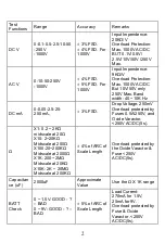
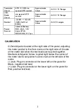


6
2.
Connect the BLACK test lead to the “-COM” jack and the RED
test lead to the“+” jack.
3. Check the needle position and the get the reading on V.A scale.
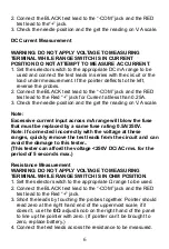
DC Current Measurement
WARNING: DO NOT APPLY VOLTAGE TO MEASURING
TERMINAL WHILE RANGE SWITCH IS IN CURRENT
POSITION DO NOT ATTEMPT TO MEASURE AC CURRENT
.
1. Set the selector switch to the appropriate DC mA range to be
used and connect the test leads in series with the circuit or the
load under measurement. If the pointer deflects to the left,
reverse the probes.
2. Connect the BLACK test lead to th
e “-COM” jack and the RED
test lead to the Red “+” jack for Current at/less than 0.25A.
3. Check the needle position and the get the reading on V.A scale.
Note:
Excessive current input across mA range will blow the fuse
that must be replaced by a same fuse rating 0.5A/250V.
Note: If connected incorrectly with the voltage at these
ranges, quickly remove the test leads from the circuit and can
avoid the damage to this tester..
(This tester can afford the voltage <250V DC/AC rms. for the
period of 5 seconds max.)
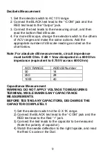
Resistance Measurement
WARNING: DO NOT APPLY VOLTAGE TO MEASURING
TERMINAL WHILE RANGE SWITCH IS IN OHM POSITION
.
1. Set the selector switch to the appropriate
Ω range to be used.
2.
Connect the BLACK test lead to the “-COM” jack and the RED
test lead to
the Red “+” jack.
3. Short the leads by touching the probes together. Pointer should
read zero at the right hand end of the uppermost scale, if it
doesn’t, use the
0
Ω
adjust knob on the right hand of the panel
to line up the pointer with zero. (If pointer
can’t be brought to
zero, replace battery.)
4. Connect the test leads across the resistance to be measured.


