ul. Elewatorska 23/1, 15-620 B
iałystok, Poland
Phone: +48 85 678-34-00, Fax: +48 85 651-15-31
www.promotech.eu
e-mail:
[email protected]
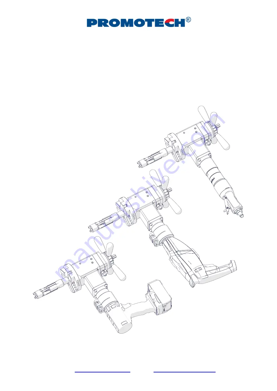
OPERATOR’S MANUAL
P
R
O
5
B
/
E
C
PIPE BEVELLING MACHINE
Page 1: ...ewatorska 23 1 15 620 Białystok Poland Phone 48 85 678 34 00 Fax 48 85 651 15 31 www promotech eu e mail office promotech eu OPERATOR S MANUAL P PR RO O 5 5 P PB B P PB BE E P PB BC C PIPE BEVELLING MACHINE ...
Page 2: ... 8 Troubleshooting the cordless electric motor 15 3 9 Replacing the spindle disk 16 3 10 Facing and bevelling at the same time 17 4 ACCESSORIES 18 4 1 Tool bits for carbon steel 18 4 2 Tool bits for stainless steel 20 4 3 Cutting fluid 21 4 4 Electric motor 21 4 5 Electric motor attachment set 21 4 6 Air motor 22 4 7 Air preparation unit 22 4 8 75 mm spindle disk 22 4 9 140 mm spindle disk set 23 ...
Page 3: ...diameters from 25 mm to 33 mm 0 98 1 30 1 2 Technical data PRO 5 PB PRO 5 PBE PRO 5 PBC Pressure 0 6 MPa 87 psi Voltage 1 110 120 V 50 60 Hz 1 220 240 V 50 60 Hz 18 V DC 5 2 Ah Air motor Modec NT10RT0851FCA1F CO Electric motor Metabo BE1100 Metabo BS 18 LTX Impuls Connection CEJN 410 DN 10 4 R 1 2 BSPT coupling Electrical plug Battery connection Air consumption 1400 Nl min 50 CFM Power 800 W 1100 ...
Page 4: ...PRO 5 PB PBE PBC This document is protected by copyrights Copying using or distributing without permission of PROMOTECH is prohibited 4 380 mm 15 232 mm 9 539 mm 21 577 mm 23 433 mm 17 232 mm 9 ...
Page 5: ...g elements Bevelling machine without tool bits 1 unit Metal box 1 unit Expanding mandrel 1 unit 118 mm spindle disk 1 unit Jaw blocks number 1 2 3 4 5 6 3 sets Coolant container 1 unit Tool container 1 unit 13 mm socket wrench 1 unit 6 mm hex wrench 1 unit 5 mm hex wrench 1 unit 4 mm hex wrench with handle 1 unit 3 mm hex wrench with ball end 1 unit Operator s Manual 1 unit 434 mm 17 468 mm 18 4 2...
Page 6: ... electric motor Spoke handle Clearance adjustment unit Expanding mandrel Spindle disk Air motor ON OFF lever Air connection Draw nut Feed indicator ON switch lock ON OFF switch Rotation direction switch must be set as shown Gear switch Speed adjustment dial LED Rotation direction switch must be set as shown ON OFF switch with speed adjustment Gear switch Torque adjustment dial Battery LED activati...
Page 7: ...s 10 Avoid unintentional starts Do not lay the machine so that the motor will start and never carry the machine with air motor by using the ON OFF lever 11 Keep the machine dry and never expose it to rain snow or frost 12 Keep the work area well lit clean and free of obstacles 13 Never use machine near flammable liquids or gases or in explosive environments 14 Secure the pipe to prevent it from fa...
Page 8: ... coating to protect the machine from rust when not in use for any extended period 24 Maintain the machine and install remove parts and tool bits only when the machine is unplugged from the air power source 25 Repair only in a service center appointed by the seller 26 If the machine falls from any height is wet or has any other damage that could affect the technical state of the machine stop the op...
Page 9: ...1 43 55 1 69 2 17 1 54 66 2 2 13 2 61 2 64 7 76 9 2 55 3 03 3 74 9 87 1 2 95 3 43 4 85 2 97 4 3 35 3 83 5 94 8 107 3 73 4 21 6 Use the 3 mm hex wrench to join the jaw blocks to the expanding mandrel 1 Fig 2 Then select up to three tool bits suitable to planned use and place them in the sockets with blades directed according to the rotation direction 2 Next tighten each tool bit with two of the scr...
Page 10: ...s until the mandrel engages with the machine completely Then tighten the set screw 4 and check whether the spoke handles can be rotated in both directions easily If the screw is too tight readjust it Finally tighten the lock nut 5 Fig 3 Installing the mandrel into the machine If the expanding mandrel becomes loose causing vibrations of the tool bits during machining perform the above actions witho...
Page 11: ...2 and tighten the motor by rotating it to the left 3 Fig 4 Installing the air motor a and an electric motor b To install an electric motor slide the clamping ring 4 onto the machine Then screw the driver 5 into the motor and insert the motor into the machine 6 by placing the arbor in the socket 2 and tighten the clamping ring with the 6 mm hex wrench 7 Finally set the rotation direction switch to ...
Page 12: ... the assembled machine into the pipe 1 Fig 5 so that the tool bit s is placed at the distance of at least 3 mm 0 12 from the pipe end Then expand the jaw blocks to the inside diameter of the pipe by rotating the draw nut 2 to the right with the 13 mm socket wrench The jaw blocks must be installed beyond the end preparation location 3 Fig 5 Clamping the machine into the pipe 2 1 3 3 ...
Page 13: ...r 2 3 seconds which will prevent rusting and degrading of the rotor vanes 3 6 Operating After the machine is connected to a proper supply press the ON OFF lever to start For the machine with an electric motor set the gear 1 and in cordless motor the maximum torque and then press and hold the ON OFF switch To lock the switch in the position ON not available in cordless press the ON switch lock befo...
Page 14: ...ugh feed 0 08 0 15 mm 0 003 0 006 per rotation to stay under the work hardened surface If the machine with electric motor becomes overloaded the motor will be shut off automatically However prevent the motor from overloading and if possible machine hard materials with not too fast feed rate and rotational speed After the pipe end is machined completely discontinue rotating the spoke handles and al...
Page 15: ...he motor shutting off automatically The brushes must be replaced with new ones by the manufacturer of the electric motor 3 8 Troubleshooting the cordless electric motor The machine with cordless electric motor has a protection system that automatically shuts off the motor when it is continuously overloaded for extended periods To stop the beeping signal that sounds in such a case release the ON OF...
Page 16: ...e the 6 mm hex wrench to loosen the set screw 1 Fig 7 by at least one turn Then rotate the spoke handles to the left 2 to disengage the mandrel from the machine 3 Fig 7 Removing the mandrel from the machine Use the 5 mm hex wrench 1 Fig 8 and remove the spindle disk 2 Then install the new disk 3 onto the pin 4 and tighten with the same screws Fig 8 Replacing the spindle disk 1 2 3 1 2 3 4 ...
Page 17: ...e time When facing and bevelling is performed at the same time use either short or long bevelling tool bit depending on the pipe diameter Fig 9 Fig 9 Positioning the facing tool bit and a short or long bevelling tool bit F0 30 facing tool bit Short tool bit Long tool bit Short tool bit Short or long tool bit Long tool bit Long tool bit Short or long tool bit Short tool bit ...
Page 18: ...031 F0 30 0 facing tool bit NOZ 000032 B30 30 bevelling tool bit NOZ 000033 B30d 30 bevelling tool bit NOZ 000036 B375 37 5 bevelling tool bit NOZ 000037 B375d 37 5 bevelling tool bit NOZ 000040 B45 45 bevelling tool bit NOZ 000041 B45d 45 bevelling tool bit for diameters over 56 mm if works together with 0 facing tool bit for diameters under 83 mm if works together with 0 facing tool bit ...
Page 19: ...of PROMOTECH is prohibited 19 NOZ 000052 IC15 40 on the left 15 internal calibration tool bit NOZ 000053 IC15 40 on the right for diameters over 56 mm 15 internal calibration tool bit NOZ 000058 J10 R6 10 J bevelling tool bit NOZ 000057 J15 R2 15 J bevelling tool bit NOZ 000059 J20 R8 20 J bevelling tool bit ...
Page 20: ... F0 30 0 facing tool bit TiAlN coated NOZ 000034 NB30 30 bevelling tool bit TiAlN coated NOZ 000035 NB30d 30 bevelling tool bit TiAlN coated NOZ 000038 NB375 37 5 bevelling tool bit TiAlN coated NOZ 000039 NB375d 37 5 bevelling tool bit TiAlN coated for diameters over 56 mm if works together with 0 facing tool bit for diameters under 83 mm if works together with 0 facing tool bit ...
Page 21: ...uting without permission of PROMOTECH is prohibited 21 4 3 Cutting fluid 4 4 Electric motor 4 5 Electric motor attachment set Required for connecting the electric motor with the machine Part number OLJ 000004 0 5 kg 1 1 lbs Part number ZST 0472 11 00 00 1 Part number SLN 000176 230 V ...
Page 22: ...tributing without permission of PROMOTECH is prohibited 22 4 6 Air motor 4 7 Air preparation unit 4 8 75 mm spindle disk Facilitates working in places hard to reach Part number NPD 0472 03 00 00 0 Part number filter regulator lubricator ZST 000021 Part number TRC 0472 12 00 00 0 ...
Page 23: ... 9 3 sets Install the spindle disk after previously removing the existing spindle disk Fig 7 Fig 8 Then use the following table to select jaw blocks of the set suitable to the inside diameter of the pipe to be machined and use the 3 mm hex wrench to tighten them to the expanding mandrel 1 Fig 2 Install the tool bits in the sockets and tighten the screws 3 Fig 2 with the 4 mm hex wrench Pipe inside...
Page 24: ...g or distributing without permission of PROMOTECH is prohibited 24 4 10 Ratchet wrench Allows performing the feed instead of the spoke handles To remove the feed disk and use the ratchet wrench unscrew two screws with the 4 mm hex wrench Part number KLC 000045 75 mm 2 95 ...
Page 25: ...25 mm to 33 mm 0 98 1 30 To remove the existing expanding mandrel loosen the nut and use the 6 mm hex wrench to loosen the set screw 1 Fig 3 by at least one turn Then rotate the spoke handles to the left to disengage the mandrel from the machine Next install the new mandrel into the machine 2 3 4 5 Fig 3 4 12 Cordless electric motor Part number TRZ 0472 21 00 00 0 Part number WRT 000021 includes t...
Page 26: ... 26 4 13 Cordless electric motor attachment set Required for connecting the cordless electric motor with the machine 4 14 5 2 Ah battery 4 15 Battery charger Allows recharging the battery from either 230 V or 120 V power source Part number AKM 000087 Part number ZST 0472 22 00 00 0 Part number LDW 000008 230 V CEE LDW 000010 120 V UK ...
Page 27: ... EC Declaration of Conformity We PROMOTECH sp z o o ul Elewatorska 23 1 15 620 Bialystok Poland declare with full responsibility that PRO 5 PB PIPE BEVELLING MACHINE is manufactured in accordance with the following standard EN ISO 12100 and satisfies safety regulations of the guideline 2006 42 EC Bialystok 7 April 2014 ___________________________ Marek Siergiej CEO ...
Page 28: ...TECH sp z o o ul Elewatorska 23 1 15 620 Bialystok Poland declare with full responsibility that PRO 5 PBE PIPE BEVELLING MACHINE is manufactured in accordance with the following standards EN 60745 1 EN 55014 EN ISO 12100 and satisfies safety regulations of the guidelines 2004 108 EC 2006 95 EC 2006 42 EC Bialystok 7 April 2014 ___________________________ Marek Siergiej CEO ...
Page 29: ... of Conformity We PROMOTECH sp z o o ul Elewatorska 23 1 15 620 Bialystok Poland declare with full responsibility that PRO 5 PBC PIPE BEVELLING MACHINE is manufactured in accordance with the following standard EN ISO 12100 and satisfies safety regulations of the guideline 2006 42 EC Bialystok 31 May 2016 ___________________________ Marek Siergiej CEO ...
Page 30: ...by copyrights Copying using or distributing without permission of PROMOTECH is prohibited 30 6 QUALITY CERTIFICATE Machine control card PRO 5 PB PBE PBC PIPE BEVELLING MACHINE Serial number Quality control Adjustments inspections Quality control ...
Page 31: ...chine to be free of defects in material and workmanship under normal use for a period of 12 months from the date of sale This warranty does not cover tool bits as well as damage or wear that arise from misuse accident tempering or any other causes not related to defects in workmanship or material Date of production Serial number Date of sale Signature of seller 1 05 31 May 2016 WE RESERVE THE RIGH...