background image


EN – ENGLISH (Original instructions) 

Operating Instructions 

 
Dear Customer, 
Many thanks for the confidence you have shown in us with the purchase of your new machine. This 

manual has been  prepared for the owner and operators  of  a PROMAC  sander  to  promote  safety 

during  installation,  operation  and  maintenance  procedures.  Please  read  and  understand  the 

information contained in these operating instructions and the accompanying documents. To obtain 

maximum life and efficiency from your machine, and to use the machine safely, read this manual 

thoroughly and follow instructions carefully. 

Table of Contents  


1. 

Declaration of conformity 

2. 

Warranty 

3. 

Safety 

Authorized use  

General safety notes  

Remaining hazards 

4. 

Machine specifications Technical data 

5. 

UNPACKING AND CHECKING LIST  

6. 

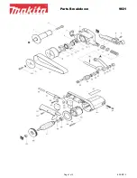
323BF-BP Exploded View 

7. 

323BF-BP Part List 


1.  Declaration of conformity 


On our own responsibility we hereby declare that 

this product complies with the regulations* listed 

on page2.


Designed in consideration with the standards**. 

2.  Warranty 


Tool  France  guarantees  that  the  supplied 

product  is  free  from  material  defects  and 

manufacturing faults. 
This warranty does not cover any defects which 

are  caused,  either  directly  or  indirectly,  by 

incorrect use, carelessness, accidental damage, 

repair, inadequate maintenance or cleaning and 

normal wear and tear. 
Any  warranty  details  (i.e.  warranty  period)  can 

be found in the General Terms and Conditions 

(GTC)  that  are  integral  part  of  the  contract. 

These GTC can be viewed at the website of your 

dealer or sent to you upon request. 
Tool France reserves the right to make changes 

to the product and accessories at any time. 
 

3. Safety 


3.1 Authorized use 

This sander is designed for sander metal and a 

similar sander only. Machining of other materials 

is  not  permitted  and  may  be  carried  out  in 

specific  cases  only  after  consulting  with  the 

manufacturer. 
The  proper  use  also  includes  compliance  with 

the  operating  and  maintenance  instructions 

given in this manual. 
The machine must be operated only by person’s 

familiar with its operation and maintenance and 

who are familiar with its hazards. 
The required minimum age must be observed. 
The machine must only be used in a technically 

perfect condition. 
When  working  on  the  machine,  all  safety 

mechanisms and covers must be mounted. 
In addition to the safety requirements contained 

in  these  operating  instructions  and  your 

country’s  applicable  regulations,  you  should 

observe the generally recognized technical rules 

concerning  the  operation  of  metalworking 

machines. 
Any other use exceeds authorization. 
In the event of unauthorized use of the machine, 

the manufacturer renounces all liability and the 

responsibility  is  transferred  exclusively  to  the 

operator. 
 

3.2 General safety notes 

Metalworking machines can be dangerous if not 

used  properly.  Therefore,  the  appropriate 

general technical rules as well as the following 

notes must be observed. 

Summary of Contents for 323BF-BP

Page 1: ...ander Bandschleifmaschine Touret bande 10 2020 France TOOL FRANCE 9 Rue des Pyr n es 91090 LISSES France www promac fr 323BF BP UK TOOL FRANCE SARL Unit 1a Stepnell Park Off Lawford Road Rugby CV21 2U...

Page 2: ...chinenrichtlinie Directive Machines 2014 30 EU electromagnetic compatibility elektromagnetische Vertr glichkeit compatibilit lectromagn tique 2011 65 EU RoHS directive RoHS Richtlinie Directive RoHS d...

Page 3: ...st mask if the cutting operation produces dust 8 Don t force the tool It will give a better and safer performance when used on jobs for which it was designed 9 Avoid accidental starting Ensure that th...

Page 4: ...or a vise to hold work It is safer than using your hands and prevents round or odd shaped pieces from turning 21 Don t overreach Keep proper footing and balance at all times Wear oil resistant rubber...

Page 5: ...e warranty period can be found in the General Terms and Conditions GTC that are integral part of the contract These GTC can be viewed at the website of your dealer or sent to you upon request Tool Fra...

Page 6: ...stable on firm and levelled table surface Make sure that the power cord does not impede work and cause people to trip Keep the floor around the machine clean and free of scrap material oil and grease...

Page 7: ...m the power source 3 3 Remaining hazards When using the machine according to regulations some remaining hazards may still exist Thrown work pieces and work piece parts can lead to injury Dust and nois...

Page 8: ...ing Knob 3 Traking Knob 2 Belt Tension Knob Eye Eye Shield Safety Cover Working Area 1 Tension Locking Knob Turn counter clockwise about 180 before adjusting tension of sanding belt or changing sandin...

Page 9: ...9 UNPACKING AND CHECKING LIST LOOSE PARTS IN RECTANGLE BOX GRINGER ASSEMBLY Q TY 1...

Page 10: ...10 LOOSE PARTS IN RECTANGLE BOX...

Page 11: ...11 LOOSE PARTS IN RECTANGLE BOX Ref No Part Name Q ty 1 Adaptor 1 2 Disc Washer 1 3 Buffer 1 4 Disc Washer 1 5 Hex Washer 1 6 Rotor Shaft Cap 1 7 Polisher Cover 1 1 2 3 4 5 6 7...

Page 12: ...luminum roller downward and locate sanding belt on the center of two rollers 3 Turn belt tension knob counter clockwise 120 back to tie belt up 1 Fix protection sheet by 3 screws 2 Fix protection cove...

Page 13: ...ng knob 3 4 Clockwise loosen the hex nut Part No 58 by a supplied 12mm open spanner 3 5 Turn adjusting rod Part No 59 clockwise to increase belt tension NOTE 1 Each clockwise turning of adjusting rod...

Page 14: ...fix it to the shaft 9 Curve Sanding 1 Put frame assembly to horizontal position 2 Loosen screw A and B showed in figure 3 open roller covers to proper position and fix it 4 This machine is now ready f...

Page 15: ...tment procedures until the tension is satisfactory 8 Repeat the procedures of hand test power test for belt balance as the fig 4 page 11 9 After adjusting belt tension before operating turn tension lo...

Page 16: ...8 323BF BP Exploded View...

Page 17: ...M 323020 1 Fan 1 21 PM 323021 Wiring Housing 1 22 PM 323022 Wiring 1 25 PM 323025 Ball Bearing 1 26 PM 323026 Left Support 1 34 TS 2172032 Machine Screw 3 16 x 1 2 4 35 PM 323035 Screw 1 38 TS 2172022...

Page 18: ...1504071 Cap Screw M8 x 35L 3 86 PM 323085 Rubber Roller 1 87 PM 323086 Sanding Belt 1 88 PM 323087 Hex Nut Left Thread 7 8 1 89 TS 1504061 Cap Screw M8 x 30L 1 90 PM 323089 Set Block 1 91 PM 323090 Wo...

Page 19: ...16 18NCx1 5 Hex Bolt 5 16 Spring Washer M8 Washer M8x18x2t 1 2 3 4 5 6 7 8 2 2 1 4 2 6 6 8 Ref No Parts Name Deseription Q ty Stand Bottom Plate Hex Bolt M8X20L Spring Washer M8 Washer M8x30x3t Washer...

Page 20: ...h Motor Chip Inlet 5 4 Chip Inlet 4 1 5 Hose 4 Clamp 4 5 Screw M5x8 Screw M6x16 Washer M6x25x2t Screw M6x12 Washer M6x18x2t 1 2 3 4 5 6 7 8 9 10 11 12 1 1 4 6 4 2 2 1 2 6 4 4 Ref No Parts Name Deserip...

Page 21: ...l circuit diagram Electrical components parts list Item Designation Description Function Magnetic contactor Overload Protector Cable 400VAC 10A 1 8 2 5 2 4A VCTF4x0 75mm2 CE IEC947 Technical Data Rema...

Page 22: ...tensity of 300 LUX is the least of value to be supplied FOR THREE PHASE 1 Electrical connection 1 1 A cable with four wires is equipped to connect your machine into the 3 phase power supply Please con...

Page 23: ...n Sie es nur an einer spezialisierten Entsorgungsstelle Dieses Symbol verweist auf die getrennte Sammlung von Elektro und Elektronikger ten gem Forderung der WEEE Richtlinie 2012 19 EU Diese Richtlini...

Page 24: ...Unfallsch den Reparaturen oder unzureichende Wartungs oder Reinigungsarbeiten sowie durch nat rliche Abnutzung durch den Gebrauch verursacht werden Weitere Einzelheiten zur Garantie k nnen den allgem...

Reviews: