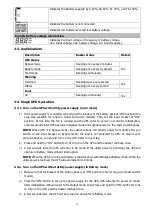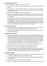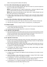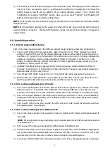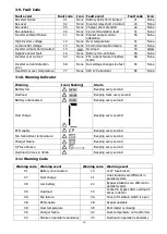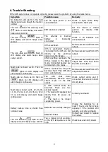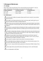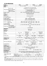
24
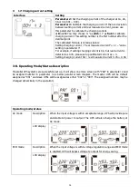
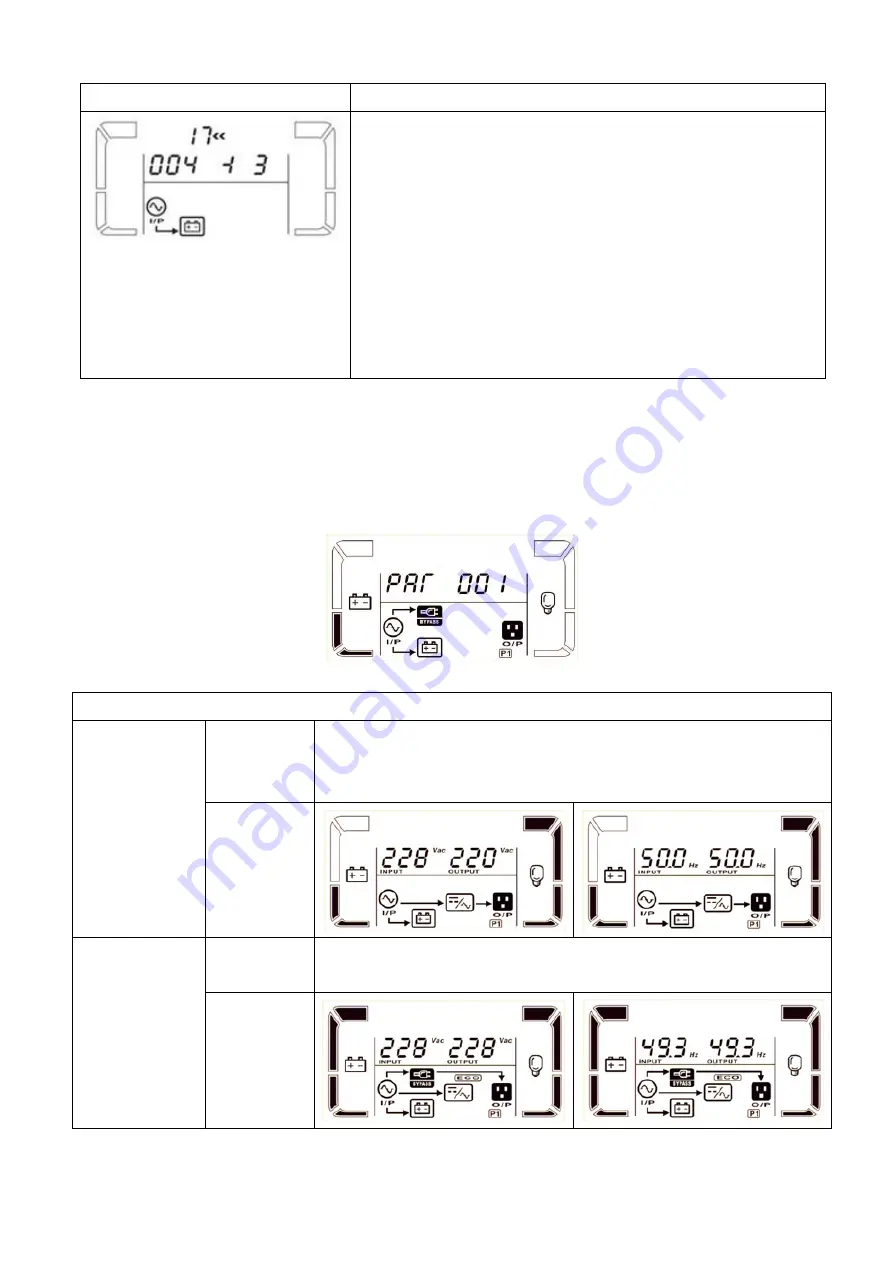
17: Charging current setting
Interface
Setting
Parameter 2:
Set the charging current of the charger at 1A, 2A,
3A or 4A (001 ~ 004).
Parameter 3:
Calibrate the charging current. If there is deviation
between setting current and real measured current, please use
this parameter to calibrate the charging current.
± 0~± 5:
You may choose
‘+’
as
add
or
‘-‘
as
Sub
to calibrate
charging current. This setting number is the first number after the
decimal point.
The calibrated formula is listed as below:
Setting charging current = “real measured current” + or – “value
setting in parameter 3”
For example, if setting charging current is 4A, but real current is
detected as 3.7A, please set up calibrated current as + 3.
Setting charging current 4A = real measured current 3.7A + 0.3A
3-8. Operating Mode/Status Description
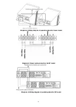
If parallel UPS systems are successfully set up, it will show one more screen with “PAR” in parameter 2 and
be assigned number in parameter 3 as below parallel screen diagram. The master UPS will be default
assigned as “001” and slave UPSs will be assigned as either “002” or “003”. The assigned numbers may be
changed dynamically in the operation;
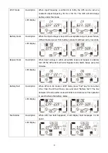
Operating mode/status
AC mode
Description
When the input voltage is within acceptable range, UPS will provide pure
and stable AC power to output. The UPS will also charge the battery at
AC mode.
LCD display
ECO mode
Description
When the input voltage is within voltage regulation range and ECO mode
is enabled, UPS will bypass voltage to output for energy saving.
LCD display

