17
5)
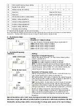
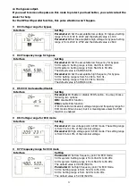
For example, you want to have charging current in 4A, but in fact, the charging current is measured
only 3.7A. Then, you need to select “+” and change the number to 4 in parameter 3. It means the
setting charging current will be added 0.3A as output charging current. Then, confirm this
modification by pressing “ON/Enter” button. Now, you may press “Test/UP” and “Mute/Down”
buttons at the same time to exit the setting mode.
NOTE 1:
Be careful that the maximum charging current should not exceed the maximum battery
charging current.
NOTE 2
:
All parameter settings will be saved only when UPS shuts down normally with internal or
external battery connection. (Normal UPS shutdown means turning off input breaker in bypass/no
output mode).
3-5. Parallel Operation
3-5-1. Parallel system initial startup
First of all, please make sure all of the UPSs are parallel models and have the same configuration.
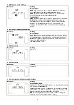
1) Turn on each UPS to AC mode respectively (Refer to section 3-4-1). Then, measure the output
voltage of each UPS to check if the voltage difference between actual output and setting value is
less than 1.5V (typical 1V) with multimeter. If the difference is more than 1.5V, please calibrate the
voltage by configuring inverter voltage adjustment (Refer to Program 15, section 3-7) in LCD
setting. If voltage difference remains more than 1.5V after calibration, please contact your local
distributor or service center for help.
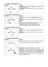
2) Calibrate the output voltage measurement by configuring output voltage calibration (Refer to
Program 16, section 3-7) in LCD setting to make sure the error between real output voltage and
detected value of UPS is less than 1V.
3) Turn off each UPS (Refer to section 3-4-7.). Then, follow the wiring procedure in section 2-4.
4) Remove the cover of parallel share current cable port on the UPS, connect each UPS one by one
with the parallel cable and share current cable, and then screw the cover back.
3-5-2. Turn on the parallel system in AC mode
1) Turn on the input breaker of each UPS. After all UPSs enter to bypass mode, measure the voltage
between output L1 of each UPS with multimeter. If the voltage difference is less than 1V, that
means all connections are correct. Otherwise, please check if the wirings are connected correctly.
2) Turn on the output breaker of each UPS. Before turning on each UPS in turns, check if PARXXX is
displayed in each UPS sequentially. If no “PARXXX” exists in any UPS, please check if the parallel
cables are connected correctly.
3) Turn on each UPS in turns. After a while, the UPSs will enter to AC mode synchronously and then,
the parallel system is completed.
3-5-3. Turn on the parallel system in Battery mode
1) Turn on the battery breaker (only available in long-run model and RT model) and output breaker of
each UPS.
NOTE:
It’s not allowed to share one battery pack in parallel system. Each UPS should be connected
to its battery pack.
2) Turn on any UPS. A few seconds later, the UPS will enter to battery mode.
3) Press the “ON” button to set up the power supply for another UPS, check if PARXXX is displayed. If
not, please check if the parallel cables are connected correctly. Then Turn on another UPS. A few
seconds later, the UPS will enter to battery mode and add to the parallel system.
4) If you have the third UPS, follow the same procedure of 3). Then, the parallel system is complete.

