background image

15

CROMOSPOT300

3.6 MODALITÀ MASTER/SLAVE

Questa modalità consente di collegare in linea più unità CROMOSPOT300 senza un controller. La prima 

unità sarà impostata come master e le altre funzioneranno come slave con lo stesso effetto.

• 

Premere il tasto MENU fino a quando sul display  non appare 

[RUNMODE]

, quindi premere il tasto ENTER 

per confermare la scelta.

• 

Selezionare con i tasti UP/DOWN nel sottomenu la voce 

[RUN]

 e confermare la scelta premendo il tasto 

ENTER.

• 

Premere i tasti UP/DOWN e selezionare la modalità 

[SLAVE]

 per impostare le unità come slave.

• 

Sull’unità master selezionare il programma desiderato come indicato al paragrafo 3.4.

• 

Servirsi dei connettori DMX del CROMOSPOT300 e di un cavo XLR per formare una catena di unità. In 

certe condizioni e lunghezze si consiglia di effettuare una terminazione come mostrato a pagina 17.

3.7 COLLEGAMENTO

Si possono collegare più unità affinché tutte le unità secondarie abbiano lo stesso effetto luce dell’unità 

principale (Master).

1.  Collegare l’uscita DMX OUT dell’unità principale con l’ingresso DMX IN della prima unità secondaria 

servendosi di un cavo XLR a 3 o 5 poli.

2.  Collegare l’uscita DMX OUT della prima unità secondaria con l’ingresso DMX IN della seconda unità 

secondaria ecc.

3.8 CONFIGURAZIONE CANALI DMX

Il CROMOSPOT300 dispone di diverse configurazioni dei canali DMX a cui si può accedere dal pannello di 

controllo.

• 

Premere il tasto MENU fino a quando sul display non appare 

[PERSON]

, quindi premere il tasto ENTER.

• 

Premere il tasto UP/DOWN per selezionare la configurazione DMX desiderata tra 

[PERSON1]

 e 

[PERSON2]  

quindi premere il tasto ENTER.

• 

Premere il tasto MENU per tornare indietro o attendere alcuni secondi per uscire dal menu di impostazione.

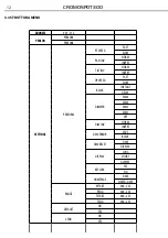
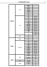
Le tabelle a pagina 18 indicano le modalità di funzionamento e i relativi valori DMX. Come interfaccia 

DMX, l’unità possiede dei contatti XLR a 3 e 5 poli.

3.9 MODALITÀ DMX

• 

Per abilitare la modalità DMX, premere il tasto MENU fino a quando sul display non appare 

[RUNMODE]

quindi premere il tasto ENTER.

• 

Selezionare con i tasti UP/DOWN nel sottomenu la voce 

[RUN]

 e confermare la scelta premendo il tasto 

ENTER.

• 

Premere il tasto UP/DOWN e selezionare la modalità 

[DMX512]

• 

Premere il tasto ENTER per confermare.

3.10 INDIRIZZAMENTO DMX

• 

Per impostare l’indirizzo DMX, premere il tasto MENU fino a quando sul display non appare 

[ADDRESS]

quindi premere il tasto ENTER.

• 

Premere il tasto UP/DOWN per selezionare il valore desiderato (

001-512

); tenere premuto invece il tasto 

UP/DOWN per  lo scorrimento veloce.

• 

Premere il tasto ENTER per confermare l’impostazione.

• 

Premere il tasto MENU per tornare indietro o attendere qualche secondo per uscire.

Summary of Contents for Cromospot300

Page 1: ...EN IT Manuale Utente User Manual CROMOSPOT300 MOVING HEAD MENU ENTER UP DOWN 001 P1...

Page 2: ...arziale per propri scopi commerciali vietata Al fine di migliorare la qualit dei prodotti la Music Lights S r l si riserva la facolt di modificare in qualunque momento e senza preavviso le specifiche...

Page 3: ...utomatica 3 5 Programmazione personalizzata 3 6 Modalit Master Slave 3 7 Collegamento 3 8 Configurazione canali DMX 3 9 Modalit DMX 3 10 Indirizzamento DMX 3 11 Collegamenti della linea DMX 3 12 Costr...

Page 4: ...on apportare modifiche all unit Tutti gli interventi devono essere sempre e solo effettuati da personale tecnico qualificato Rivolgersi al pi vicino centro di assistenza tecnica autorizzato Se si desi...

Page 5: ...delle Condizioni Generali di Garanzia Si prega dopo l acquisto di procedere alla registrazione del prodotto sul sito www musiclights it In alternativa il prodotto pu essere registrato compilando e in...

Page 6: ...llici open 56 possibili effetti di sovrapposizione Effetto gobo shake e rotazione continua selezionabile Gruppo gobos di facile accesso attraverso pannello rimovibile sul corpo mobile Ruota effetti co...

Page 7: ...atico degli effetti in seguito a spostamenti accidentali Sospensione e fissaggio qualsiasi posizione per mezzo di supporti omega inclusi Alimentazione Alimentazione 100 240V 50 60Hz Consumo ad emissio...

Page 8: ...CROMOSPOT300 8 1 2 ELEMENTI DI COMANDO E DI COLLEGAMENTO MENU ENTER DOWN UP ON 0 I OFF FUSE T3 15A Vista A 2 3 A 1 B Vista B 4 5 6 7 9 8 10 Fig 1...

Page 9: ...so le diverse funzioni o aumentare il valore della funzione stessa Tasto DOWN per scorrere attraverso le diverse funzioni o diminuire il valore della funzione stessa 5 INTERRUTTORE ON OFF 6 POWER IN s...

Page 10: ...da inserire nelle apposite sedi della piastra dove vengono bloccati con una rotazione in senso orario fino all arresto L area di collocazione deve avere una stabilit sufficiente e supportare almeno 1...

Page 11: ...BASE Il proiettore CROMOSPOT300 dispone di un display LCD e di 4 pulsanti per l accesso alle funzioni del pan nello di controllo e la loro gestione fig 3 MENU ENTER UP DOWN Per scorrere il menu princi...

Page 12: ...RM INVERT TILT INV NORM INVERT OP SPEED FAST SLOW BLACK INSTANT DELAY DIMMER DIM4 DIM3 DIM2 DIM1 OFF DIM INV NORM INVERT DMX ERROR SAVE BLACK DMX RESET DMX DISPLAY DISPLAY LONG SHORT ALWAYS KEYLOCK YE...

Page 13: ...ROT 000 255 PRI ROT 000 255 FOCUS 000 255 DIMMER 000 255 STROBE 000 255 TIME 000 255 USE NO YES SEND NO YES MANUAL RESET NO YES DMXVALUE PAN 000 255 TILT 000 255 COLOR 000 255 GOBO1 000 255 GOBO2 000...

Page 14: ...ne personalizzata modificando il valore di ciascuna funzione Premere il tasto MENU fino a quando sul display non appare RUNMODE quindi premere il tasto ENTER per confermare la scelta Selezionare con i...

Page 15: ...condaria ecc 3 8 CONFIGURAZIONE CANALI DMX Il CROMOSPOT300 dispone di diverse configurazioni dei canali DMX a cui si pu accedere dal pannello di controllo Premere il tasto MENU fino a quando sul displ...

Page 16: ...anno assegnate automaticamente agli indirizzi successivi Segue un esempio con indirizzo 33 di start e una configurazione a 14 e 11 canali DMX DMX Address 33 DMX Address 75 DMX Address 47 DMX Address 6...

Page 17: ...ndi l uscita DMX con l ingresso DMX della successiva unit l uscita di quest ultima con l ingresso di quella successiva e via dicendo finch tutte le unit sono collegate formando una catena Per installa...

Page 18: ...0 CH Function in PERSON1 Value 7 Shaking gobo 8 Shaking gobo 7 Shaking gobo 6 Shaking gobo 5 Shaking gobo 4 Shaking gobo 3 Shaking gobo 2 Shaking gobo 1 Flow effect 091 105 106 120 121 135 136 150 151...

Page 19: ...59 160 191 192 223 224 255 14 CONTROL No function Pan Tilt black activated Pan Tilt black deactivated Fan automatic Fan slow Fan standard Fan high speed Auto1 Auto2 Test Custom Sound1 Sound2 Reset No...

Page 20: ...Function in PERSON2 Value 4 Shaking gobo 5 Shaking gobo 4 Shaking gobo 3 Shaking gobo 2 Shaking gobo 1 Flow effect 136 150 151 165 166 180 181 195 196 210 211 255 5 GOBO 2 No Gobo Gobo 1 Gobo 2 Gobo...

Page 21: ...11 CONTROL No function Pan Tilt black activated Pan Tilt black deactivated Fan automatic Fan slow Fan standard Fan high speed Auto1 Auto2 Test Custom Sound1 Sound2 Reset No function DIM 0 DIM 1 DIM 2...

Page 22: ...nzione dimmer Selezionare NORMAL per l impostazione normale op pure INVERT per il controllo invertito della funzione DMX ERROR Gestione in caso di errore del segnale DMX SAVE consente di salvare gli u...

Page 23: ...tasto MENU per tornare indietro o attendere qualche secondo per uscire dal menu di impostazione 3 15 MODALIT MANUALE Per il CROMOSPOT300 possibile effettuare le seguenti regolazioni di funzioni Reset...

Page 24: ...il tasto MENU fino a quando sul display non appare SERVICE quindi premere il tasto ENTER Selezionare nel sottomenu CONTENT e premere il tasto ENTER per confermare la scelta Premere il tasto UP DOWN p...

Page 25: ...veri e grassi La frequenza con la quale effettuare le operazioni sotto indicate dipende da diversi fattori quali la quantit di movimenti degli effetti e la qualit dell ambiente di lavoro umidit dell a...

Page 26: ...ne A e tirare nella direzione B fig 9 5 Togliere l anello di sicurezza fig 10 sul gobo con un utensile adatto e prelevare il gobo 6 Non svitare le viti sul portagobos perch tengono insieme il cuscinet...

Page 27: ...e il gruppo ottico correttamente Il proiettore non alimentato Mancanza di alimentazione di rete Cavo di alimentazione danneggiato Alimentatore interno difettoso Verificarelapresenzadellatensionealimen...

Page 28: ...6 Plastic body slam shut 17 Fan 18 Head fan fixed plate 19 LED board 20 Lens 21 Heat sink 22 40 lens support A No ITEM 23 Stepping motor 24 Driver board 25 Color board 26 Fixed pattern plate 27 40 len...

Page 29: ......

Page 30: ...by any means for any commercial use In order to improve the quality of products Music Lights S r l reserves the right to modify the characteristics stated in this instruction manual at any time and w...

Page 31: ...3 Menu structure 3 4 Operation in automatic mode 3 5 Edit custom program 3 6 Master Slave mode 3 7 Linking 3 8 DMX configuration 3 10 DMX addressing 3 11 Connection of the DMX LINE 3 12 Construction...

Page 32: ...always be carried out by qualified technical personnel Contact the nearest sales point for an inspection or contact the manufacturer directly If the unit is to be put out of operation definitively tak...

Page 33: ...te www musiclights it Please remember to register the piece of equipment soon after you purchase it logging on www musiclights it The product can be also registered filling in and sending the form ava...

Page 34: ...nt through slot n lock panel Effect wheel with 3 facet prism rotating in both directions at different speed Easy show built in programs with automatic sound activated mode enabled by LCD control panel...

Page 35: ...5 CROMOSPOT300 Power supply Power unit 100 240V 50 60Hz Max power consumption 120 W Power connection Locking IEC Weight and dimensions Weight 10 kg Dimensions WxHxD 330x270x473 mm...

Page 36: ...CROMOSPOT300 6 1 2 OPERATING ELEMENTS AND CONNECTIONS MENU ENTER DOWN UP ON 0 I OFF FUSE T3 15A View A 2 3 A 1 B View B 4 5 6 7 9 8 10 Fig 1...

Page 37: ...hrough the menu list or increase the value of the current function DOWN button scroll down through the menu list or decrease the value of the current function 5 ON OFF SWITCH 6 POWER IN mains plug for...

Page 38: ...e and turned clockwise until they lock to the stop The mounting place must be of sufficient stability and be able to support a weight of 10 times of the unit s weight When carrying out any installatio...

Page 39: ...n switch off the unit with the power switch 3 2 BASIC The CROMOSPOT300 has a LCD display and 4 button used to access the control panel functions and man age them fig 3 MODE UP DOWN ENTER Used to acces...

Page 40: ...RM INVERT TILT INV NORM INVERT OP SPEED FAST SLOW BLACK INSTANT DELAY DIMMER DIM4 DIM3 DIM2 DIM1 OFF DIM INV NORM INVERT DMX ERROR SAVE BLACK DMX RESET DMX DISPLAY DISPLAY LONG SHORT ALWAYS KEYLOCK YE...

Page 41: ...ROT 000 255 PRI ROT 000 255 FOCUS 000 255 DIMMER 000 255 STROBE 000 255 TIME 000 255 USE NO YES SEND NO YES MANUAL RESET NO YES DMXVALUE PAN 000 255 TILT 000 255 COLOR 000 255 GOBO1 000 255 GOBO2 000...

Page 42: ...STEP PAN TILT COLOR GOBO1 GOBO2 GOBO2 ROT PRI ROT FOCUS DIMMER STROBE and TIME Press the ENTER button to confirm Set the value 000 255 through the buttons UP DOWN Enter USE and select YES to run the s...

Page 43: ...MODE and press the button ENTER to confirm Select in submenu RUN press ENTER button to confirm the choice Press UP DOWN button to select DMX512 Press the button ENTER to store 3 10 DMX ADDRESSING Pres...

Page 44: ...nd controller operation Over long runs can be necessary to insert a DMX level matching amplifier For those connections the use of balanced microphone cable is not recommended because it cannot transmi...

Page 45: ...long the cable when they reach es the end of the line under certain conditions and with certain cable lengths this could cause them to cancel the original signals The termination is prepared by solder...

Page 46: ...Function in PERSON1 Value 7 Shaking gobo 8 Shaking gobo 7 Shaking gobo 6 Shaking gobo 5 Shaking gobo 4 Shaking gobo 3 Shaking gobo 2 Shaking gobo 1 Flow effect 091 105 106 120 121 135 136 150 151 165...

Page 47: ...59 160 191 192 223 224 255 14 CONTROL No function Pan Tilt black activated Pan Tilt black deactivated Fan automatic Fan slow Fan standard Fan high speed Auto1 Auto2 Test Custom Sound1 Sound2 Reset No...

Page 48: ...fast 000 060 061 150 151 165 166 255 7 PRISM PRISM ROTATION White light Prism but not turn Anti clockwise rotate from slow to fast Prism but not turn Clockwise rotate from slow to fast 000 004 005 00...

Page 49: ...11 CONTROL No function Pan Tilt black activated Pan Tilt black deactivated Fan automatic Fan slow Fan standard Fan high speed Auto1 Auto2 Test Custom Sound1 Sound2 Reset No function DIM 0 DIM 1 DIM 2...

Page 50: ...erted control of dimming function DMX ERROR Control in case of DMX signal errors Select SAVE to save the latest data DMX on error DMX signal BLACK allows you to activate the mode on error DMX blackout...

Page 51: ...carry out full fixture reset Press the ENTER button to confirm Press the MENU button to go back or wait some seconds for automatic exit from the menu Manual control Press the button MENU so many time...

Page 52: ...h UP DOWN button To move forward the next letter press ENTER button to turn back instead press MENU button Send display content Press the button MENU so many times until the display shows SERVICE then...

Page 53: ...ally clean the parts subject to dust and grease deposits The frequency with which the following operations are to be carried out depends on various factors such as the amount of the effects and the qu...

Page 54: ...4 Push the gobo plate follow the direction A and pull out the plate follow the direction B fig 9 5 Move the ring over the gobo away fig 10 so you can take out the gobo 6 Never release the screws on th...

Page 55: ...assembly Misaligned lens assembly Clean the fixture regularly Install lens assembly properly Fixture does not power up No power Loose or damaged power cord Faulty internal power supply Check for powe...

Page 56: ...6 Plastic body slam shut 17 Fan 18 Head fan fixed plate 19 LED board 20 Lens 21 Heat sink 22 40 lens support A No ITEM 23 Stepping motor 24 Driver board 25 Color board 26 Fixed pattern plate 27 40 len...

Page 57: ...conseguenti sono a carico del possessore dell apparecchio A tutti gli effetti la validit della garanzia avallata unicamente dalla presentazione del certificato di garanzia The guarantee covers the un...

Page 58: ...ate Data acquisto FORM TO BE FILLED IN AND MAILED CEDOLA DA COMPILARE E SPEDIRE FORM TO BE FILLED IN AND KEPT CEDOLA DA COMPILARE E CONSERVARE PROV ZIP CODE C A P MODEL MODELLO SERIAL N SERIE N Purcha...

Page 59: ......

Page 60: ...39 0771 721955 www musiclights it info musiclights it Music Lights S r l entertainment technologies ISO 9001 2008 Certified Company 2012 Music Lights S r l PROLIGHTS un brand di propriet della Music L...

Reviews: