background image

Recommended Maintenance                                                                                                                        JB-70 


13 

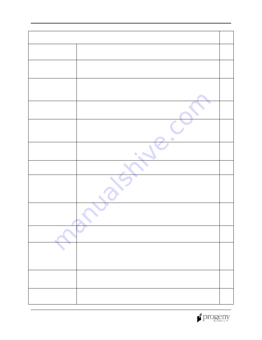
System Function Checklist 


Wall Mounting 

Ensure that the wall support is adequate and that the system is properly 
mounted to the wall. 


Labels 

Ensure that all certified components bear labels that include the model 
and serial number, date of manufacture and a statement of certification 
as noted elsewhere in this manual. 


Indication of 
Technique 
Factors 

Verify that the “70 kV – 8 mA” is legible on the label of the Operator 
Panel. 


Tubehead 

Check for oil leaks or other evidence that could indicate internal damage.  
Replace the Tubehead, if necessary. 


Tubehead 
Rotation 

Ensure that the Tubehead maintains its position around the horizontal 
axis while remaining easy to rotate and position. Also, check the vertical 
pivot of the Tubehead for easy movement while remaining in position 
after movement. 


Suspension 

Check that all movements are smooth and quiet. Verify that the 
Tubehead is properly counterbalanced for vertical drift and that the 
Horizontal and Articulating Arms do not drift horizontally. 


Power Switch 

Verify that the switch is working properly and that the Ready Indicator is 
illuminated when the power switch is in the ON position. 


Operator Panel 
Controls 

With the power switch, located at the base of the Control Unit, in the ON 
position, verify that a time indicates on the Operator Panel. Also, check 
the function of the selection buttons for Exposure Time, Tooth Selection, 
Image Receptor Type and Patient Size. Pressing a selection button 
should cause indicator lamps to indicate the selected item. 


Exposure Button 

Verify that the Exposure button on the Operator Panel is functioning 
properly. To make an exposure, press and hold the Exposure button until 
the Radiation Indicator is extinguished and the audible signal is no 
longer heard. 


Exposure 
Indicators 

Make several exposures and verify that the Radiation Indicator 
illuminates and the audible signal is heard. 


Premature 
Termination 

Select an exposure of 1.65 seconds (2.0 seconds for the 50 Hz system) 
using the Exposure Time buttons. Initiate an exposure but release the 
Exposure button after a brief period of time before the timer terminates 
the exposure.  Verify that exposure terminates immediately upon release 
of the Exposure button. 


Coil-cord Hand 
Switch (Optional) 

If a coil-cord hand switch is used, inspect the switch housing and coil 
cord for damage or wear.  Replace if evidence of damage is present. 


User Information 

Make certain that the user of the system has received a copy of the User 
Manual. 


Summary of Contents for I7016

Page 1: ...JB 70 Dental X Ray System User Manual 00 02 1568 Rev A Progeny Dental 1407 Barclay Boulevard Buffalo Grove Illinois 60089 U S A Phone 888 924 3800 Fax 847 459 5175 WWW progenydental com...

Page 2: ...Progeny Dental 2002 Patents Pending...

Page 3: ...JB 70 Dental X Ray System 9 Operator Panel Controls 9 Taking an X Ray 10 Using the 12 in Cone 30 A2033 11 Recommended Maintenance 12 Regular Maintenance 12 Cleaning and Disinfecting 12 Checking Syste...

Page 4: ...Table of Contents JB 70 ii...

Page 5: ...e Articulating Arm provides the articulation support for the Tubehead and the reach and coverage of the Tubehead to the patient The Articulating Arm allows smooth movement for precise positioning and...

Page 6: ...General Information JB 70 4 Figure 1 Component Diagram...

Page 7: ...ment UL 2601 1 File Number E181750 Classified by Underwriters Laboratories Inc with respect to electrical shock fire and mechanical hazards only in accordance with UL 2601 1 and CAN CSA C22 2 NO 601 1...

Page 8: ...ollowing regulatory documents apply 21CFR UL 2601 1 IEC 60601 1 2 IEC 60601 1 3 IEC 60601 2 7 IEC 60601 2 28 IEC 60601 2 32 Medical Device directive ISO 13485 EN46001 Declaration Progeny Inc declares...

Page 9: ...tional Electrical code or VDE standards concerning provisions of an additional protective earth ground terminal for power supply connection Before cleaning or disinfecting this equipment must always b...

Page 10: ...ATION SEULEMENT PAR DU PERSONNEL AUTORISE VOIR MANUEL DE L OPERATEUR WARNING X RAY THIS X RAY UNIT MAY BE DANGEROUS TO PATIENT AND OPERATOR UNLESS SAFE EXPOSURE FACTORS AND OPERATING INSTRUCTIONS ARE...

Page 11: ...can also be adjusted using the up and down Exposure Time arrows For a table of the pre programmed exposure times set at the factory refer to the Pre programmed Exposure Times table later in this manua...

Page 12: ...eceptor Type is selected 4 Verify that the system is set for the appropriate Patient Size The icon for the currently selected Patient Size is illuminated The change the Patient Size press the Patient...

Page 13: ...one 30 A2033 is recommended when using the paralleling film positioning technique Using the long cone requires the use of longer exposure times which can be programmed into the system by changing an i...

Page 14: ...roblems are resolved Regular Maintenance In the interest of equipment safety a regular maintenance program must be established This maintenance program should consist of cleaning and disinfecting as w...

Page 15: ...is in the ON position Operator Panel Controls With the power switch located at the base of the Control Unit in the ON position verify that a time indicates on the Operator Panel Also check the functi...

Page 16: ...programmed exposure times make sure that the proper image receptor type is selected 2 Verify proper operation of the film processor No X Ray If no x ray is produced check the following 1 Verify that t...

Page 17: ...an be modified using the procedure that follows the table Times for 8 inch 20 cm Cone in Seconds 60 Hz 50 Hz times shown in parentheses Digital Receptor D speed Film E F Speed Film Tooth Selection Adu...

Page 18: ...ld Incisor 0 133 0 160 0 100 0 120 0 417 0 500 0 200 0 240 0 233 0 280 0 117 0 140 Bicuspid 0 167 0 200 0 083 0 100 0 533 0 640 0 267 0 320 0 333 0 400 0 167 0 200 Bitewing 0 200 0 240 0 100 0 120 0 4...

Page 19: ...e time is to be changed a Use the Image Receptor Type button to select the receptor type b Use the Tooth Selection button to select a tooth c Use the Patient Size button to select the patient size 3 U...

Page 20: ...50 Hz operation Timer Accuracy 34 ms Source to Skin Distance 8 inch 20 cm 12 inch 30 cm Radiation Output Approximately 800 mR at the following sets 70 kVp 8 mA 1 0 sec 20 cm SID Minimum Inherent Filtr...

Page 21: ...adiation produced during this time is small it is useful and contributes to forming the image on the film When the exposure time starts the first several x ray pulses will be high kVp about 80 low mA...

Reviews: