
24
1
8
#8 x 1/2" Ground Screw
2
6
3/8" x 3 1/4" Screw
3
10
3/8" Star Washer
4
31
#8 x 3/4" Screw
5
8
5/16" x 3/4" Screw
6
8
5/16" Star Washer
7
4
#8 x 1" Screw
8
2
#10 x 1 1/2" Screw
9
2
3/8" x 2 1/2" Bolt
10
1
Incline Motor Spacer
11
2
M6 x 50mm Screw
12
2
3/8" x 1" Bolt
13
3
Hood Clip
14
19
#8 x 3/4" Truss Head Screw
15
1
3/8" x 1 3/4" Bolt
16
6
3/8" Jam Nut
17
2
1/4" x 3/8" Screw
18
4
#8 x 1/2" Screw
19
4
5/16" x 1 1/2" Bolt
20
4
5/16" Nut
21
2
Upper Handrail Cap
22
2
#8 Star Washer
23
4
1/4" Star Washer
24
2
Drive Roller Washer
25
2
1/4" x 1 1/4" Screw
26
2
Incline Frame Washer
27
1
Left Foot Rail
28
2
Platform Cushion
29
1
Caution Decal
30
2
Belt Guide
31
1
Drive Roller/Pulley
32 1 Magnet
33
1
Reed Switch
34
1
Reed Switch Clamp
35
1
Drive Motor
36 1 Controller
37
1
Controller Plate
38 1 Frame
39
1
Walking Platform
40
1
Walking Belt
41
1
Right Foot Rail
42
1
Idler Roller
43
1
Left Rear Foot
44
1
Hex Key
45
1
5/32" Hex Key
46
1
Right Rear Foot
47
1
Console Ground Wire
48
1
Motor Hood
49
1
Incline Motor
50
2
Lift Frame Bushing
51
1
Lift Frame
52
1
Belly Pan
53
1
Power Cord Grommet
54
1
Power Cord
55
1
Power Switch
56
4
1/4" x 3 1/2" Screw
57 1 Console
58
1
Console Base
59
1
Left Handrail
60
2
Lower Handrail Cap
61
1
Console Crossbar
62 1 Key/Clip
63
1
Upright Wire
64
1
Right Handrail
65
2
Upper Body Arm Insert
66
1
Left Upright
67
1
Latch Housing
68
1
Latch Pin Assembly
69
2
Warning Decal
70
4
Base Cap
71
2
Thick Base Pad
72
2
Thin Base Pad
73
1
Upright Grommet
74 1 Base
75 2 Wheel
76
1
Right Upright
77
2
Lift Frame Pin
78
8
#8 x 3/4" Tek Screw
79
2
1/4" Star Washer
80
1
3/8" x 1 1/2" Bolt
81
2
Wire Tie
82
1
Latch Spacer
83
2
Console Clamp
84
1
Left Upper Body Arm
85
1
Right Upper Body Arm
86
2
#10 x 3/4" Screw
87
8
#10 Flat Washer
*
–
User’s Manual
Key No. Qty.
Description
Key No. Qty.
Description
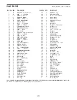
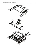
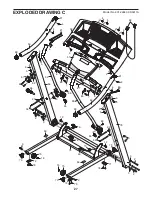
PART LIST
Model No. 831.24843.0 R0911A
Note: Specifications are subject to change without notice. For information about ordering replacement parts, see
the back cover of this manual. *These parts are not illustrated.