background image

2

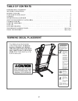
WARNING DECAL PLACEMENT

This drawing shows the location(s) 

of the warning decal(s). If a decal is 

missing or illegible, call 1-888-533-

1333 and request a free replacement 

decal. Apply the decal in the location 

shown. Note: The decal(s) may not be 

shown at actual size.

256836

TABLE OF CONTENTS

WARNING DECAL PLACEMENT . . . . . . . . . . . . . . . . . . . . . . . . . . . . . . . . . . . . . . . . . . . . . . . . . . . . . . . . . . . . . . .2

IMPORTANT PRECAUTIONS . . . . . . . . . . . . . . . . . . . . . . . . . . . . . . . . . . . . . . . . . . . . . . . . . . . . . . . . . . . . . . . . . .3

BEFORE YOU BEGIN. . . . . . . . . . . . . . . . . . . . . . . . . . . . . . . . . . . . . . . . . . . . . . . . . . . . . . . . . . . . . . . . . . . . . . . .5

PART IDENTIFICATION CHART. . . . . . . . . . . . . . . . . . . . . . . . . . . . . . . . . . . . . . . . . . . . . . . . . . . . . . . . . . . . . . . .6

ASSEMBLY . . . . . . . . . . . . . . . . . . . . . . . . . . . . . . . . . . . . . . . . . . . . . . . . . . . . . . . . . . . . . . . . . . . . . . . . . . . . . . . .7

OPERATION AND ADJUSTMENT   . . . . . . . . . . . . . . . . . . . . . . . . . . . . . . . . . . . . . . . . . . . . . . . . . . . . . . . . . . . . .13

 HOW TO FOLD AND MOVE THE TREADMILL  . . . . . . . . . . . . . . . . . . . . . . . . . . . . . . . . . . . . . . . . . . . . . . . . . . .19

TROUBLESHOOTING   . . . . . . . . . . . . . . . . . . . . . . . . . . . . . . . . . . . . . . . . . . . . . . . . . . . . . . . . . . . . . . . . . . . . . .20

EXERCISE GUIDELINES  . . . . . . . . . . . . . . . . . . . . . . . . . . . . . . . . . . . . . . . . . . . . . . . . . . . . . . . . . . . . . . . . . . . .23

PART LIST. . . . . . . . . . . . . . . . . . . . . . . . . . . . . . . . . . . . . . . . . . . . . . . . . . . . . . . . . . . . . . . . . . . . . . . . . . . . . . . .24

EXPLODED DRAWING. . . . . . . . . . . . . . . . . . . . . . . . . . . . . . . . . . . . . . . . . . . . . . . . . . . . . . . . . . . . . . . . . . . . . .25

ORDERING REPLACEMENT PARTS. . . . . . . . . . . . . . . . . . . . . . . . . . . . . . . . . . . . . . . . . . . . . . . . . . .  Back Cover

90-DAY FULL WARRANTY . . . . . . . . . . . . . . . . . . . . . . . . . . . . . . . . . . . . . . . . . . . . . . . . . . . . . . . . . . .  Back Cover

Summary of Contents for PRO-FORM CROSSWALK 397 831.24843.0

Page 1: ...ipment Keep this manual for future reference Model No 831 24843 0 Serial No Write the serial number in the space above for reference Serial Number Decal Assembly Operation Maintenance Part List and Drawing Sears Roebuck and Co Hoffman Estates IL 60179 TREADMILL EXERCISER User s Manual ...

Page 2: ...location shown Note The decal s may not be shown at actual size TABLE OF CONTENTS WARNING DECAL PLACEMENT 2 IMPORTANT PRECAUTIONS 3 BEFORE YOU BEGIN 5 PART IDENTIFICATION CHART 6 ASSEMBLY 7 OPERATION AND ADJUSTMENT 13 HOW TO FOLD AND MOVE THE TREADMILL 19 TROUBLESHOOTING 20 EXERCISE GUIDELINES 23 PART LIST 24 EXPLODED DRAWING 25 ORDERING REPLACEMENT PARTS Back Cover 90 DAY FULL WARRANTY Back Cover...

Page 3: ... Do not use an extension cord 12 Use only a single outlet surge suppressor that meets all of the specifications described on page 13 To purchase a surge suppres sor see your local Sears store or call the telephone number on the back cover of this manual and order part number 146148 or see your local electronics store 13 Failure to use a properly functioning surge suppressor could result in damage ...

Page 4: ... 23 Never insert any object into any opening on the treadmill 24 Inspect and properly tighten all parts of the treadmill regularly 25 DANGER Always unplug the power cord immediately after use before clean ing the treadmill and before performing the maintenance and adjustment procedures described in this manual Never remove the motor hood unless instructed to do so by an authorized service represen...

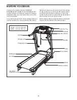
Page 5: ... this manual To help us assist you note the product model number and serial number before contacting us The model number and the location of the serial number decal are shown on the front cover of this manual Before reading further please familiarize yourself with the parts that are labeled in the drawing below BEFORE YOU BEGIN Length 5 ft 5 in 165 cm Width 2 ft 9 in 84 cm Handrail Storage Latch C...

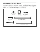
Page 6: ...is manual The number following the key number is the quantity used for assembly Note If a part is not in the hardware kit check to see if it is preat tached If it is not call 1 888 533 1333 Extra hardware may be included 8 x 3 4 Screw 4 4 3 8 x 3 1 4 Screw 2 6 3 8 Star Washer 3 10 1 4 x 3 1 2 Screw 56 4 10 x 1 1 2 Screw 8 2 8 x 1 Screw 7 4 1 4 Star Washer 23 4 1 4 Star Washer 23 4 8 x 1 2 Ground S...

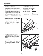
Page 7: ...ubricant on top of the walking belt or on the shipping carton This is normal If there is lubricant on top of the walking belt wipe it off with a soft cloth and a mild non abrasive cleaner To identify small parts see page 6 Assembly requires the following tools the included hex keys one Phillips screwdriver scissors To avoid damaging parts do not use power tools 1 ASSEMBLY B A 74 2 Locate the Uprig...

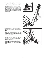
Page 8: ...e Base 74 do not fully tighten the Screws yet Attach the Left Upright not shown in the same way Note There are no wires on the left side 76 3 3 2 74 63 5 4 Identify the Right Upright 76 which is marked Right Have a second person hold the Right Upright near the Base 74 See the inset drawing Tie the wire tie in the Right Upright 76 securely around the end of the Upright Wire 63 Then insert the Uprig...

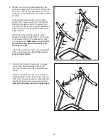
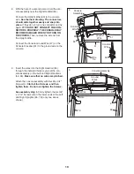
Page 9: ...o of the 5 16 x 3 4 Screws 5 and two of the 3 8 Star Washers 6 that you just removed Make sure not to pinch the Upright Wire 63 Start both Screws and then tighten them Attach the Left Handrail 59 to the Left Upright 66 as described above Note There are no wires on the left side 6 6 5 5 5 5 6 6 6 59 66 76 64 5 6 5 6 63 7 64 6 5 5 5 6 6 61 47 59 7 Position the Console Crossbar 61 between the Left an...

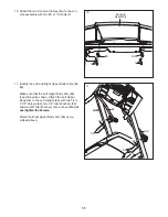
Page 10: ...re 47 on the Console Crossbar 61 to the ground wire on the console 64 8 63 61 Console Wire Ground Wire Console Assembly Console Wire 63 Wire Tie 47 9 9 Insert the wires into the Right Handrail 64 through the indicated hole as you set the con sole assembly on the Left and Right Handrails 59 64 Make sure that no wires are pinched Attach the console assembly with four 8 x 3 4 Screws 4 Start all four ...

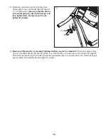
Page 11: ...ght Upper Body Arms 84 85 Make sure that the Left Upper Body Arm 84 is positioned as shown Attach the Left Upper Body Arm to the Left Upright 66 with two 1 4 x 3 1 2 Screws 56 two 1 4 Star Washers 23 and two 3 8 Star Washers 3 as shown Do not overtighten the Screws Attach the Right Upper Body Arm 85 as de scribed above 11 66 3 23 3 56 56 84 85 23 ...

Page 12: ...ot to over tighten the Screws 13 Make sure that all parts are properly tightened before you use the treadmill If there are sheets of plas tic on the treadmill decals remove the plastic To protect the floor or carpet place a mat under the treadmill Note Extra hardware may be included Keep the included hex keys in a secure place one of the hex keys is used to adjust the walking belt see pages 21 and...

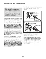
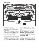
Page 13: ...n appropri ate outlet that is properly installed and grounded in accordance with all local codes and ordinances IMPORTANT The treadmill is not compatible with GFCI equipped outlets and may not be compatible with AFCI equipped outlets This product is for use on a nominal 120 volt circuit see drawing 1 A temporary adapter may be used to connect the surge suppressor to a 2 pole receptacle if a proper...

Page 14: ...f the treadmill as it guides you through an effective exercise session To turn on the power see page 15 To use the manual mode see page 15 To use a preset work out see page 17 To use the information mode see page 18 IMPORTANT If there is a sheet of clear plastic on the console remove the plastic To prevent dam age to the walking platform wear clean athletic shoes while using the treadmill The firs...

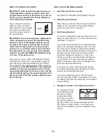
Page 15: ...UAL MODE 1 Insert the key into the console See HOW TO TURN ON THE POWER at the left 2 Select the manual mode When the key is inserted the manual mode will be selected If a preset workout has been selected remove the key and then reinsert it 3 Start the walking belt To start the walking belt press the Start button the Speed increase button or one of the speed buttons numbered 1 through 10 If you pr...

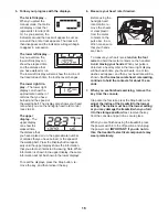
Page 16: ...ile information is shown in the upper display the same information will not be shown in the lower displays To reset the displays press the Stop button re move the key and then reinsert the key 6 Measure your heart rate if desired Before using the handgrip heart rate monitor re move the sheets of clear plastic from the metal contacts on the pulse bar In ad dition make sure that your hands are clean...

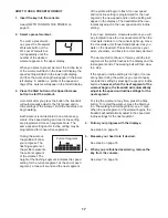
Page 17: ... and the next segment of the profile will begin to flash If a new speed and or incline setting is programmed for the next segment the new speed and or incline setting will appear in the displays The treadmill will then au tomatically adjust to the new speed and or incline setting If you have selected a crosswalk workout you will be prompted to use the crosswalk arms When the crosswalk indicator on...

Page 18: ...atures a display demo mode designed to be used if the treadmill is displayed in a store While the demo mode is turned on the console will function normally when you plug in the power cord press the power switch into the reset position and insert the key into the console However when you remove the key the displays will remain lit although the buttons will not function If the demo mode is turned on...

Page 19: ...dmill fold it as described at the left CAUTION Make sure that the latch pin is fully inserted into the platform cushion Moving the treadmill may require two people 1 Hold the frame and one of the handrails and place one foot against a wheel 2 Pull back on the handrail until the treadmill will roll on the wheels and carefully move it to the desired location CAUTION Do not move the treadmill without...

Page 20: ...tch see the drawing above If the switch has tripped wait for five minutes and then press the switch back in b Make sure that the power cord is plugged in If the power cord is plugged in unplug it wait for five minutes and then plug it back in c Remove the key from the console and then reinsert it d If the treadmill still will not run please see the front cover of this manual SYMPTOM The console di...

Page 21: ...ease button again When the incline is calibrated remove the key from the console SYMPTOM The walking belt slows when walked on a Use only a single outlet surge suppressor that meets all of the specifications described on page 13 b If the walking belt is overtightened treadmill per formance may decrease and the walking belt may become damaged Remove the key and UNPLUG THE POWER CORD Using the hex k...

Page 22: ...ng belt is correctly tightened you should be able to lift each edge of the walking belt 2 to 3 in 5 to 7 cm off the walking platform Be careful to keep the walk ing belt centered Then plug in the power cord insert the key and carefully walk on the treadmill for a few minutes Repeat until the walking belt is properly tightened SYMPTOM The upperbody arms squeak during use a Note Correcting this prob...

Page 23: ...ic Exercise If your goal is to strengthen your cardiovascular system you must perform aerobic exercise which is activity that requires large amounts of oxygen for prolonged periods of time For aerobic exercise adjust the intensity of your exercise until your heart rate is near the highest number in your training zone WORKOUT GUIDELINES Warming Up Start with 5 to 10 minutes of stretch ing and light...

Page 24: ... 32 Hex Key 46 1 Right Rear Foot 47 1 Console Ground Wire 48 1 Motor Hood 49 1 Incline Motor 50 2 Lift Frame Bushing 51 1 Lift Frame 52 1 Belly Pan 53 1 Power Cord Grommet 54 1 Power Cord 55 1 Power Switch 56 4 1 4 x 3 1 2 Screw 57 1 Console 58 1 Console Base 59 1 Left Handrail 60 2 Lower Handrail Cap 61 1 Console Crossbar 62 1 Key Clip 63 1 Upright Wire 64 1 Right Handrail 65 2 Upper Body Arm Ins...

Page 25: ...2 33 14 30 29 31 41 18 19 19 45 20 44 27 28 14 34 37 1 20 36 14 28 14 14 14 14 11 14 14 14 43 46 11 42 17 35 77 77 25 25 19 19 4 38 24 24 22 20 20 79 79 14 1 1 1 14 14 14 14 87 87 87 87 14 14 14 87 87 87 14 87 Model No 831 24843 0 R0911A ...

Page 26: ...26 EXPLODED DRAWING B 52 4 4 54 53 48 13 51 80 15 16 16 1 49 4 55 4 4 4 26 26 50 50 13 13 4 4 4 4 10 16 16 Model No 831 24843 0 R0911A ...

Page 27: ...72 78 72 78 78 71 78 71 69 16 75 70 70 8 67 70 2 3 2 3 3 2 62 59 6 4 63 63 73 64 60 1 4 70 12 12 4 81 76 4 82 5 5 6 6 5 5 6 60 7 7 61 57 58 56 23 3 56 23 3 65 86 47 85 1 83 84 86 4 4 4 4 4 4 4 4 4 4 5 6 5 6 65 83 21 21 Model No 831 24843 0 R0911A ...

Page 28: ... S A or maintenance agreement Canada on a product serviced by Sears 1 800 827 6655 U S A 1 800 361 6665 Canada Para pedir servicio de reparación a domicilio y para ordenar piezas 1 888 SU HOGAR 1 888 784 6427 Get it fixed at your home or ours Registered Trademark TM Trademark SM Service Mark of Sears Brands LLC Marca Registrada TM Marca de Fábrica SM Marca de Servicio de Sears Brands LLC 90 DAY FU...

Reviews: