5
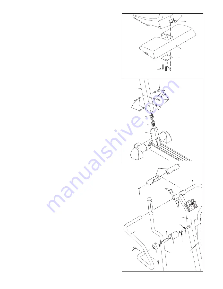
3. Have another person hold the Upright (2) in the posi-
tion shown.
Connect the Upper Wire Harness (30) to the Lower
Wire Harness (42). Insert the connectors on the Wire
Harnesses up into the Upright (2). Carefully pull the
upper end of the Upper Wire Harness to remove
the slack from the Wire Harnesses.
Slide the Upright (2) onto the Frame (1). Be careful to
avoid pinching the Wire Harnesses (30, 42). Attach
the Upright with six M10 x 20mm Button Screws (49)
and six M10 Split Washers (73). Be careful to avoid
damaging the Wire Harnesses with the Button
Screws. Do not tighten the Button Screws yet.
73
73
73
49
49
49
30
42
3
4
21
31
Grease
2
85
3
22
29
25
26
69
80
81
29
4. Apply a generous amount of the included grease to
the Pivot Axle (25). Next, insert the Pivot Axle into the
Upright (2) and center it. Reapply grease to both ends
of the Pivot Axle. Orient the indicated hole as shown.
Slide an Upper Body Arm Cover (26) onto the indicat-
ed tube on an Upper Body Arm (29). Next, slide the
Upper Body Arm and the Upper Body Arm Cover onto
the left end of the Pivot Axle (25).
Have another person hold the Left Handlebar (21)
near the Upright (2). Slide a Handlebar Cover (31)
onto the lower end of the Left Handlebar.
Slide the upper end of the Left Handlebar (21) into the
tube on the front of the Upright (2), while sliding the
lower end of the Left Handlebar onto the Pivot Axle
(25). Attach the upper end of the Left Handlebar with
two M8 x 41mm Button Bolts (80) and two M8 Jam
Nuts (81); Make sure that the Jam Nuts are resting
in the hexagonal holes in the Left Handlebar.
Attach the lower end of the Left Handlebar with an M8
x 38mm Button Bolt (85) and an M8 Jam Nut (81).
Then, press the tabs on the Handlebar Cover (31) into
the Upper Body Arm Cover (26).
Repeat this step with the other Upper Body Arm
(29) and the Right Handlebar (22).
Hold the halves of the Upright Cover (3) around the
tube on the front of the Upright (2). Attach the Upright
Cover with an M4 x 16mm Round Head Screw (69).
Do not pinch the
wire harnesses
during this step.
1
2
81
2. Identify the Rear Stabilizer (6). While another person
lifts the back of the Frame (1), attach the Rear
Stabilizer to the Frame with the Support Plate (64) and
four M8 x 44mm Button Screws (84).
2
6
64
1
84
84
Tube
Hole


