background image

EN|ENGLISH 


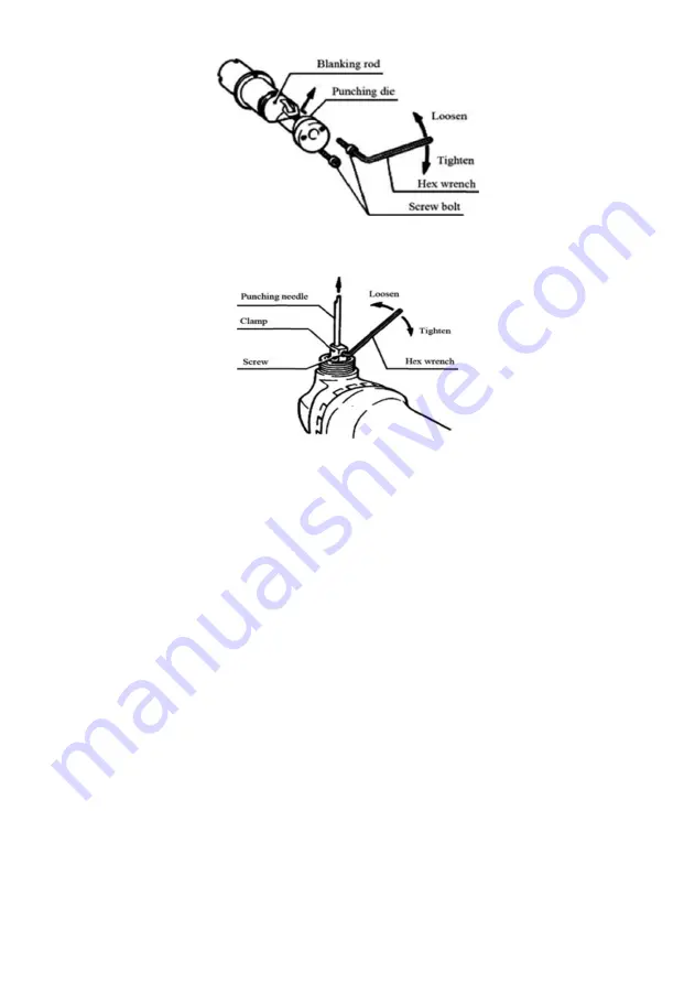
Fig 9 


Fig 10 

■ Assembly


 Installing and removing the punch and die ACaution:


Always be sure that the tool is switched off and unplugged before removing or 

installing the punch and die. 

1. Make sure to replace the punching needle and the punching die set. When 

disassembling them, loosen the cap nut with the wrench, disassemble the rod 

out of the tool, and then loosen the nut fastening the punching die with a hex 

wrench. Disassemble the punching die out of the rod, and then loosen the 

screw rod fastening the punching needle with a hex wrench. Pull the punching 

needle out of the rod.(Fig9&Fig10) 


When assembling the punching needle and the punching die, insert the 
punching needle into the clamp to make the hole face the fastening screw rod 
and then tighten it. Put the punching die into the blanking rod and tighten the 
fix screw cap. Finally, put the blanking rod into the tool to make the punching 
needle insert the tool through the hole in it and tighten the screw cap to fix 

Summary of Contents for SM1.6-1000

Page 1: ...an avoid the occurrence of accidents and incidents acquainted with the controls and following safe working procedures WARNING Read and understand all instructions Failure to follow all instructions li...

Page 2: ...erious personal injury Dress properly Do not wear loose clothing or jewelry Contain long hair Keep your hair clothing and gloves away from moving parts Loose clothes jewelry or long hair can be caught...

Page 3: ...qualified repair personnel Service or maintenance performed by unqualified personnel could result in a risk of injury When servicing a tool use only identical replacement parts Follow instructions in...

Page 4: ...efore placing it down 8 Never allow children to use the machine 9 Some material contains chemicals which may be toxic Take caution to prevent dust inhalation and skin contact Follow material supplier...

Page 5: ...F Fig6 Fig 2 Caution Before plugging it into an outlet check whether the switch works properly Press down the trigger to see whether the back switch is turned onto position OFF To switch ON Push the b...

Page 6: ...od at a desired position There are 4 fixed positions separately at 90 at 0 on the right and the left at 90 and 180 Fig 3 Thickness gauge Fig4 The recess of the holder matrix 4 is considered as a measu...

Page 7: ...ght angles 90 to the work piece being cut and push the machine slightly according to the cut direction Fig 5 cutouts Fig6 Cutouts can be done by first opening a round hole over 21 mm in diameter which...

Page 8: ...on whether to cut it at an angle or at right angles When operating the direction of holding the tool must run parallel to the corrugating direction What s more make the die cutting chip at right angle...

Page 9: ...the punching die with a hex wrench Disassemble the punching die out of the rod and then loosen the screw rod fastening the punching needle with a hex wrench Pull the punching needle out of the rod Fi...

Page 10: ...carbon brush regularly When the wearing of a carbon brush reaches the wearing limit line It should be replaced Keep the carbon brush clean and make t roll freely inside the fixer Replace the carbon br...

Page 11: ...nd due to the industrial technological and structural defects ie admitted as the fault of the manufacturer The warranty does not apply to Product malfunction resulting from 1 non compliance with the r...

Page 12: ...ct which caused the failure of the motor or other components and parts To definite signs of overload refers deformation or melt plastic parts and assemblies of the machine emergence of scale on the co...

Reviews: