phase mains monitoring)
24
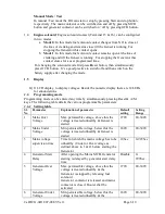
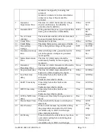
CT Ratio
Current Transformer ratio
(Available only in DGC-6 with single
phase mains monitoring)
10
1-199
1.8
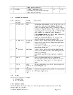
Switches Description:
S.No.
Switch
Symbol
Switch
Function
Description
1
OR A/M
Next
Normal operation mode: In this mode, next is used
to select the voltages on the display. The default
voltage is mains R Phase voltage. Y Phase, B Phase.
Generator voltage & Battery voltage can be selected
by pressing next. The corresponding LED shall light
up to indicate the parameter that is displayed.
Programming Mode: Next key is used to select the
next parameter to be programmed.
When pressed for more than 4 sec. It toggles the
mode from auto to manual and vice versa.
2
OR Start
Increment
or start
This key is only active during programming mode
and is used to increment the value of the parameter
under programming.
In manual mode this key may be used for ignition /
crank command to DG
3
-
OR Stop
Decrement
This key is only active during programming mode
and is used to decrement the value of the parameter
under programming.
In manual mode this key may be used to stop the
DG.
4
Reset
Reset
Reset key resets the Hooter and Fault signals.
The first press shall reset the hooter and next shall
reset the faults. A long press of 1 Sec shall reset
both.
5
MCB
Mains
contactor on
/ off
Mains contactor can be switched on or switched off
by pressing this key.
6.
GCB
Generator
contactor on
/ off
Generator contactor can be switched on or switched
off by pressing this key.
1.9
Faults
There are two categories of faults
1) Internal Faults
2) External faults
1.9.1
Internal Faults
Internal faults are the faults, which do not need any external signals and are detected by
the system itself. They are:
Cat/DCG-6D1I/07-08/03/Ver 1 Page 8/10
Summary of Contents for DGC-6D
Page 1: ......


