background image

43 

M-43-25 


LUF-Series Lufran Manual 

Revision  - Date 03-01-04-18                                                                                   Standard outlet, Standard Interface 

Maintenance: 

The  LUF-series  Lufran  fluoropolymer inline water heater requires only a routine inspection every 6 
months to check the operation of the various operation and safety devices.  The maintenance procedures 
listed here should only be performed by qualified technicians.  Many of these devices require the control 
system to remain operational during inspection, while others may be checked while the unit is completely 
powered down. 


Note: 

Several maintenance tasks can be completed simultaneously while the cabinet access covers 

are open and lockout/tagout procedures are in place. 


Maintenance Schedule: 

Categories of Electrical Hazards 


Type 

Description 

Equipment is energized, but live circuits are covered or insulated to prevent accidental shock. 

Equipment is energized and energized circuits of less than 24 VDC, 240 VA and 20 joules are 
exposed to accidental contact. 


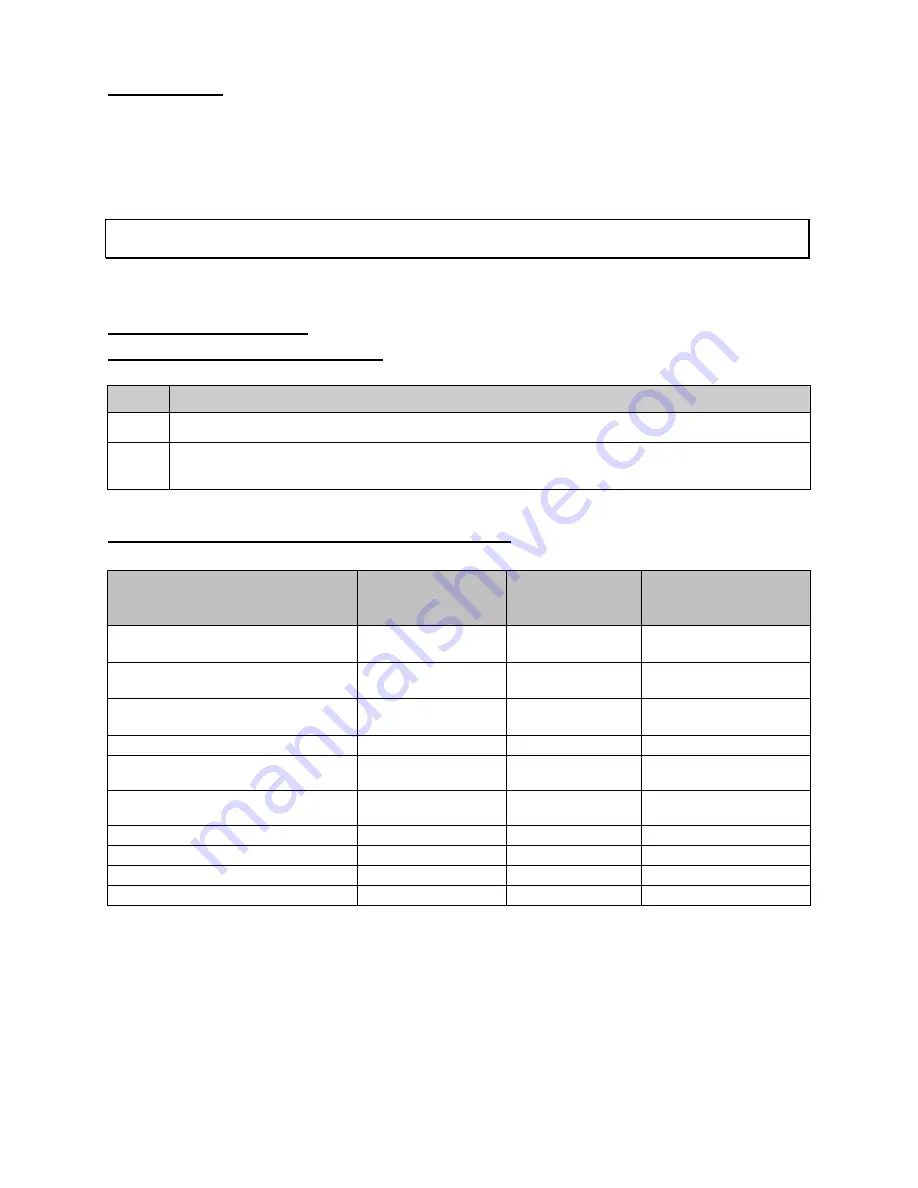
Maintenance To Be Performed Every 6 Months: 


Item to Inspect 

Lockout / Tagout 

Required (Y/N) 

Electrical Hazard 

Category (1-2) 

Procedure Number 

Outlet plumbing liquid level sensor, 
top-half plumbing 

M1 

Outlet process sensor, column TC 
sensor 

M2 

Leak detector (Optional) 

M3 

Purge gas flow switch 

M4 

Humidistat purge exhaust, humidistat 
switch 

M5 

Pressure relief valve (PRV), bottom-
half plumbing 

M6 

Cabinet cooling fans 

M7 

SSR heat sink cooling fans 

M8 

Circuit breaker 

M9 

Safety Contactor 

M10 

Summary of Contents for Lufran LUF Series

Page 1: ...TM Fluoropolymer Inline Water Heater www processtechnology com 38809 Mentor Ave Willoughby Ohio 44094 Phone 440 974 1300 Fax 440 974 9561 USA CN 800 621 1998 Optional features shown Photo may vary fro...

Page 2: ...TOR INTERFACE 15 Operator Interface Buttons 15 Operator Interface Panel OIP 15 Main Menu 16 Alarms Menu 18 Trend Graph 19 Alarm Summary 20 ADAM Setup Menu 21 SLC Setup Menu 22 Secure Menu 23 Secure Me...

Page 3: ...tion Quincy Mass 02269 Introduction The LUF series Lufran TM fluoropolymer inline water heater is designed to heat DI water with very stringent cleanliness requirements All wetted surfaces in this uni...

Page 4: ...it mener blessure b nine ou mod r e ATTENTION peut galement tre utilis pour avertir les pratiques dangereux CAUTION indicates a potentially hazardous situation which if not avoided may result in minor...

Page 5: ...formation This system features the patented DAC TM control system operating from a PLC with a touch screen operator interface The DAC control system provides superior temperature control and faster re...

Page 6: ...onal High process temperature sensor High element temperature sensor Purge gas flow switch Moisture sensor in the purge gas exhaust line Sensor failure open sensor detection Heater Power Kilowatts Flo...

Page 7: ...28 in 769mm 30 25 in 2123mm 83 57 in 340 kg 750 lbs 195kW 312kW 1220mm 48 in 769mm 30 25 in 2123mm 83 57 in 682 kg 1500 lbs Wetted surfaces Heating elements PTFE fluoropolymer Columns and plumbing PV...

Page 8: ...on the model serial number label located directly above the operator interface screen Refer to figure 33 page 41 to see the location of this label Assembly Control Circuit Power Circuit Enclosure Fast...

Page 9: ...ter Wattage W Number Of Heater Columns Wattage Per Heater Column W Heater Model Number Heater Wattage W Number Of Heater Columns Wattage Per Heater Column W 024 24 000 1 24 000 144 144 000 2 72 000 03...

Page 10: ...onnector 32mm 1 inch E Flange 19mm 3 4 inch F NPT Pipe Threads Female 13mm 1 2 inch G NPT Pipe Threads Female 19mm 3 4 inch H NPT Pipe Threads Female 25mm 1 inch I NPT Pipe Threads Male 13mm 1 2 inch...

Page 11: ...Please refer to the table below for a brief listing of the available options Heater Model Number Description C1 Ethernet communications C2 Devicenet communications C3 RS232 communications C4 RS485 com...

Page 12: ...e dimensions of the specific model are based upon the unit wattage The cabinet assembly requires ventilation Locate equipment so that ventilation fans on the top and bottom of the enclosure and louver...

Page 13: ...al service is rated and fused for the required amperage draw Ne pas d passer la tension nominale Des dommages irr parables l appareil de chauffage entra nera Do not exceed the rated voltage Irreparabl...

Page 14: ...with the instruction manual is available as a free download through their website http hosteng com C2 Option DeviceNet The C2 communications option adds DeviceNet communications to the PLC controller...

Page 15: ...t set point of the heater When the system is in NETWORK control mode this value should match address V3102 V3212 Remote control Heater output 0 System is in LOCAL control mode 1 System is in MANUAL co...

Page 16: ...tactor 1CON It illuminates to indicate the main power is off Operator Interface Panel OIP The operator interface panel is an intelligent flat panel display It is designed to interchange and display gr...

Page 17: ...e LOCAL MANUAL REMOTE These buttons will switch control of the various settings between local mode remote mode or manual adjustments of the DAC control values The selected control mode will be highlig...

Page 18: ...the process sensor located at the outlet of the heater HEATER OUTPUT Displays the output load of the heating elements needed to provide the desired outlet temperature HEAT ON OFF This button will sta...

Page 19: ...ed will be indicated by a blinking red light Refer to the Alarms section of this manual for a detailed description of each alarm setting Figure 9 Alarms Menu 2 Screens Fault Log Information Panel Desc...

Page 20: ...ging Figure 10 Trend Graph Trend Graph Information Panel Description OFF LOG This button turns on or off the data logging function When off is selected there is no trend graph data to view Pressing th...

Page 21: ...el Description PAGE UP PAGE DOWN LINE UP LINE DOWN These buttons allow the operator to scroll up and down through the list of alarm summary lines DETAIL This button will display additional details for...

Page 22: ...ls All settings listed here are set at the factory and should not be changed Figure 12 ADAM Setup Menu ADAM CFG Information Panel Description CH0 CH7 These fields show the analog sensor type for each...

Page 23: ...is a factory setting which should not be changed AL2 MOD Alarm 2 function for each module Value 6 absolute upper limit alarm This is a factory setting which should not be changed AL2 HI Alarm high li...

Page 24: ...WARE Displays the PLC software version installed in this unit REMOTE HIGH Upper scaling input value for the remote setpoint setting This setting corresponds to a 20mA input signal from the remote setp...

Page 25: ...ays the FLOW CALIBRATION screen RESET DEFAULTS This button will reset all values to factory settings HEATER CALIB This button displays the HEATER CALIBRATION screen BOOST GAIN This button allows adjus...

Page 26: ...m This is a factory setting which should not be changed AL2 HI Alarm high limit value This setting triggers the PROCESS OVERTEMP alarm AL2 LOW Alarm low limit value Not used O1 TYPE Output 1 type Valu...

Page 27: ...ROCESS SETPOINT Displays the process setpoint when in local control mode Press the process setpoint button to bring up a keypad to change its value DELTA T CALC Displays the calculated temperature ris...

Page 28: ...value taken from the RAW DATA display on this menu SLOPE CALC Calculated value from the HIGH FLOW HIGH RAW LOW FLOW and LOW RAW fields RAW DATA Information from the flow meter LOW FLOW Manually entere...

Page 29: ...ATION menu which can be reached through the SECURE MENU Figure 18 Heater Calibration Menu 1 Once the installation and startup procedure is complete insure that there is an adequate and steady flow of...

Page 30: ...ss the HIGH RAW field and using the keypad enter the number displayed in the RAW DATA field 5 Establish the lowest operating flow rate through the heater 6 Go to the back of the unit and record the fl...

Page 31: ...isconnected sensor connection Element TC Open Circuit 1 4 Element Sensor Disconnected The element over temperature sensor has failed open The sensor must be replaced This may also be caused by a disco...

Page 32: ...rophic overheat damage to the heating column The cause of the liquid level fault must be identified and corrected before the unit can be reset Purge Fault Purge Fault The purge gas pressure switch doe...

Page 33: ...ect the shock sensors located on the outside of the crate The shock sensors will indicate if the unit experienced rough handling If the sensors indicate that the unit has experienced rough handling co...

Page 34: ...ition of the unit at its place of operation Move the unit slowly as there is no means of slowing or stopping the unit Ensure that there are sufficient personnel to move the unit safely Failure to foll...

Page 35: ...the bracket halves on the cabinet The customer can decide whether to install the bottom half of the brackets to face inward or outward as shown below Plumbing The plumbing installation of this unit s...

Page 36: ...means to drain the heating columns which will be necessary in the case of replacing a heating column or some other items The following describes a recommended means of column drain 1 Install a servic...

Page 37: ...il De tels dommages ne sont pas couverts par notre garantie du produit Failure to properly secure the plastic piping when tightening the plumbing connections may result in internal damage to the plumb...

Page 38: ...m required torque value See the table for proper values 4 Repeat this procedure for each of the flared tube fittings 5 Turn on the water Establish flow through the heater Check for leaks at the fittin...

Page 39: ...r fittings tightening procedure Pressure Relief Valve PRV Connection 13mm 1 2 inch compression fitting Note 210kW 312kW models have two PRV connections 1 Loosen and remove the compression nut Remove t...

Page 40: ...t n cessaires sont correctement install s Verify that the electrical supply is shut off and any necessary lockout tagout devices are properly installed Before the electrical power is connected to this...

Page 41: ...l number on the front of the unit for power requirements 1 Remove electrical access panel on the top of the cabinet by loosening the cover mounting screws 2 Cut a hole in the access panel for the inco...

Page 42: ...and check all plumbing connections and water heater for leaks Repair any water leaks if applicable 4 Enable the power at the MAIN SERVICE DISCONNECT provided by customer 5 Ensure that the disconnect h...

Page 43: ...tomer 5 Stop water flow through the unit If the unit will be shut down will be for an extended period open the customer supplied drain located near the inlet plumbing connection to drain the water fro...

Page 44: ...kout tagout procedures are in place Maintenance Schedule Categories of Electrical Hazards Type Description 1 Equipment is energized but live circuits are covered or insulated to prevent accidental sho...

Page 45: ...f the plumbing connections on the top half of the unit for possible leaks Any leaks found must be repaired Locate the capacitance type sensor on the top outlet manifold of heating column 2 and 4 if ap...

Page 46: ...t tous les p riph riques de verrouillage d branchement n cessaires sont correctement install s Verify that the electrical supply is shut off and any necessary lockout tagout devices are properly insta...

Page 47: ...izing 2 Continue water flow through the unit for this procedure Allow the unit to cool to ambient inlet temperature 3 Open the rear cabinet door Locate the outlet process temperature sensor located in...

Page 48: ...e sensor 6 Loosen the 1 8 inch fitting and remove the sensor from the fitting 7 Insert the new sensor until the black label reaches the top of the 1 8 inch compression nut Tighten the fitting 8 Connec...

Page 49: ...ove any cable ties that hold the leak detector wiring 5 Loosen and remove the fitting that holds the leak detector to the mounting bracket 6 Slide the leak detector from the fitting on the bracket 7 I...

Page 50: ...let of the purge gas flow switch Retain the compression nuts and ferrules for use in step 13 7 Remove the tubing from the inlet and outlet connections of the purge gas flow switch Note the inlet and o...

Page 51: ...hen proceed to step 6 If moisture is present it may be caused by the following Startup following extended shutdown If the heater was shut down for an extended period but was not drained properly moist...

Page 52: ...re properly installed 3 Open the rear cabinet door 4 Remove the black plastic enclosure cover on the humidistat 5 Remove female disconnect terminal connectors 6 Remove screw from the center of the hum...

Page 53: ...discharge tubing of the PRV Confirm that there is no liquid in the discharge tube If the PRV is leaking it must be replaced 7 Confirm that the weep hole of the PRV is not leaking Procedure M6 2 PRV Re...

Page 54: ...n fitting 9 Re connect the inch discharge tubing to the PRV 10 Start flow of water to the unit and check for leaks 11 Close the rear cabinet door M7 Cabinet Cooling Fans There are two cooling fans loc...

Page 55: ...terminals Refer to the electrical print for the specific terminal numbers 5 Disconnect the fan wires from the connector plug if applicable 6 Remove the cooling fan and fan guard from the sidewall of t...

Page 56: ...should be operating continuously while power is applied Procedure M8 1 SSR Cooling Fan Inspection Procedure Open the front cabinet door Verify that the cooling fans are operating If a cooling fan has...

Page 57: ...tton to the OFF position If the unit is in REMOTE mode disable the heater from the customer supplied remote controller This will also prevent the heaters from energizing 2 Press the red POWER OFF butt...

Page 58: ...correctement install s Verify that the electrical supply is shut off and any necessary lockout tagout devices are properly installed 3 Continue water flow through the unit for this procedure Allow th...

Page 59: ...utton light base contact block 1 7383 RELAY SSR 15Amps 50VDC 1 8986 RELAY SSR Module 125Amps 600VAC One per heating column 24 52kW heat sink two SSRs overtemp thermostat cooling fan guard 1 4851 Alarm...

Page 60: ...I Water system suppler for their recommendations The bypass to the DI recirculation loop should be installed as close as possible to the process tank Confirm that the bypass plumbing will be able to w...

Page 61: ...consequential damage PROCESS TECHNOLOGY neither assumes nor authorizes any representative of PROCESS TECHNOLOGY or any other person to assume for it any other liabilities in connection with the sale...

Page 62: ...the main menu screen Enter the password default 1234 This will bring you to the first screen of the CONFIGURATION menu Press NEXT to reach the second screen of the CONFIGURATION menu 3 Press the TRIC...

Page 63: ......

Reviews: