Page 7
Page 2
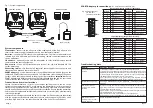
Fig.1 - System components
proWSS1 receiver
System components
Transmitter
connects to the AV source at the sending end of the link; also acts as a
receiver for remote control commands coming from the remote location.
Receiver
connects to TV display at the remote location. The receiver also contains an
infrared eye and UHF radio transmitter for sending remote control commands to the
source equipment.
IR emitters
optionally used with the transmitter to relay infrared remote control
commands to the source equipment.
Power units
used with the transmitter and receiver; for use with standard UK 13A
socket-outlets only.
Connecting cables
two identical AV cables for connecting between the source and
transmitter, and between the receiver and TV.
SCART adapters
used where necessary to convert between the phono plugs on the
cables and SCART sockets on the source and TV. Observe the colour coding of the phono
sockets, which should be matched to the plugs during installation.
Important:
the two
SCART adapters are different and cannot be interchanged between the AV source and
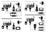
remote location ends of the link (see installation diagrams, Figs. 2 & 3).
Transmitter and receiver locations
Locate the transmitter and receiver in convenient positions near to the AV source
equipment and remote location TV. Avoid placing the transmitter or receiver on top of a
stack of other equipment as this may result in overheating. Clearance of at least 50 mm
should be allowed above and around the units for ventilation. Ensure that the transmitter
and receiver will not become smothered by fabrics (such as curtains) or by other thermally
insulating materials.
Where the link is being used toward the limit of its range it will be necessary to experiment
with the equipment locations to obtain best picture and sound quality. Positions which
provide a high clear view towards the other end of the link will usually be best.
Troubleshooting hints
m
e
l
b
o
r
P
g
n
i
w
o
ll
o
f
e
h
t
k
c
e
h
C
t
o
n
n
o
i
s
s
i
m
s
n
a
r
t
V
A
.
g
n
i
k
r
o
w
?
d
e
t
c
e
n
n
o
c
y
lt
c
e
r
r
o
c
d
n
a
p
u
-
d
e
r
e
w
o
p
t
n
e
m
p
i
u
q
e
t
n
a
v
e
l
e
r
ll
a
s
I
V
T
a
o
t
y
lt
c
e
ri
d
g
n
it
c
e
n
n
o
c
y
b
k
c
e
h
C
?
s
l
a
n
g
i
s
g
n
i
d
i
v
o
r
p
e
c
r
u
o
s
V
A
e
h
t
s
I
.)
s
l
a
u
n
a
m
t
n
e
m
p
i
u
q
e
V
A
o
t
r
e
f
e
r
,t
o
n
fi
(
r
e
tt
i
m
s
n
a
r
t
f
o
d
a
e
t
s
n
i
t
e
k
c
o
s
T
R
A
C
S
o
t
g
n
i
d
n
o
p
s
e
r
r
o
c
,t
u
p
n
i
r
o
l
e
n
n
a
h
c
V
A
t
c
e
r
r
o
c
e
h
t
o
t
t
e
s
V
T
y
a
l
p
s
i
d
e
h
t
s
I
?
d
e
t
c
e
n
n
o
c
s
i
r
e
v
i
e
c
e
r
e
h
t
h
c
i
h
w
o
t
t
e
k
c
o
s
T
R
A
C
S
e
h
t
s
d
n
e
e
h
t
e
t
a
r
a
p
e
s
n
e
h
t
)
m
o
o
r
e
m
a
s
(
e
g
n
a
r
tr
o
h
s
y
r
e
v
t
a
k
n
il
e
h
t
t
u
o
y
r
T
.
s
e
c
n
a
t
s
m
u
c
ri
c
r
a
l
u
c
it
r
a
p
r
u
o
y
r
o
f
e
g
n
a
r
f
o
ti
m
il
h
s
il
b
a
t
s
e
o
t
y
ll
a
u
d
a
r
g
.
e
r
u
t
c
i
p
n
o
e
c
n
e
r
e
fr
e
t
n
I
n
o
l
e
n
n
a
h
c
a
g
n
it
c
e
l
e
s
n
o
it
a
r
e
p
O
e
e
s
(
l
e
n
n
a
h
c
t
n
e
r
e
ff
i
d
a
g
n
i
s
u
y
r
T
.)
6
e
g
a
p
t
o
n
s
l
o
r
t
n
o
c
e
t
o
m
e
R
e
t
o
m
e
r
m
o
r
f
g
n
i
k
r
o
w
.
n
o
it
a
c
o
l
r
o
f
)
s
(t
e
s
d
n
a
h
t
c
e
r
r
o
c
e
h
t
g
n
i
s
u
e
r
a
u
o
y
e
r
A
e
h
t
?
d
e
n
r
e
c
n
o
c
t
n
e
m
p
i
u
q
e
s
t
h
g
il
t
n
e
c
s
e
r
o
u
lf
f
o
s
e
p
y
t
e
m
o
s
d
n
a
t
h
g
il
n
u
s
(
ti
n
u
r
e
v
i
e
c
e
r
e
h
t
g
n
i
v
o
m
y
r
T
.)
r
e
v
i
e
c
e
r
R
I
e
h
t
h
ti
w
e
r
e
fr
e
t
n
i
n
a
c
d
e
s
u
e
r
a
e
s
e
h
t(
r
e
v
i
e
c
e
r
d
n
a
r
e
tt
i
m
s
n
a
r
t
e
h
t
n
o
s
l
a
ir
e
a
p
i
h
w
e
h
t
g
n
i
v
o
m
y
r
T
.)
y
l
n
o
k
n
il
l
o
r
t
n
o
c
e
t
o
m
e
r
F
H
U
e
h
t
r
o
f
.t
n
e
m
p
i
u
q
e
e
c
r
u
o
s
n
o
s
r
e
tt
i
m
e
R
I
f
o
n
o
it
i
s
o
p
h
ti
w
t
n
e
m
ir
e
p
x
E
.)
k
n
il
o
e
B
O
&
B
,
s
e
x
o
b
e
l
b
a
c
l
a
ti
g
i
d
.
g
.
e
(
e
l
b
it
a
p
m
o
c
e
b
t
o
n
y
a
m
t
n
e
m
p
i
u
q
E
t
o
n
s
l
o
r
t
n
o
c
e
t
o
m
e
R
m
o
o
r
e
c
r
u
o
s
n
i
g
n
i
k
r
o
w
.)
d
n
e
r
e
tt
i
m
s
n
a
r
t(
ff
o
h
c
ti
w
S
S
W
o
r
p
.r
e
tt
i
m
s
n
a
r
t
1
S
SCART Adapter pin connections
(NC = no internal connection to pin)
Input to display (output from receiver)
proWSS1 transmitter
SCART adapters
Power unit (x2)
IR emitters
Connecting cables
(x2)
Fig.4 SCART connector
pin numbers
(view towards socket)
1
19
20
2
Output from source (input to transmitter)
.
o
n
n
i
p
n
o
i
t
c
e
n
n
o
c
1
t
u
o
o
i
d
u
a
R
2
C
N
3
t
u
o
o
i
d
u
a
L
4
)
o
i
d
u
a
(
d
n
u
o
r
G
5
C
N
6
C
N
7
C
N
8
C
N
9
C
N
0
1
C
N
.
o
n
n
i
p
n
o
i
t
c
e
n
n
o
c
1
1
C
N
2
1
C
N
3
1
C
N
4
1
C
N
5
1
C
N
6
1
C
N
7
1
)
o
e
d
i
v
(
d
n
u
o
r
G
8
1
C
N
9
1
)
S
B
V
C
(
t
u
o
o
e
d
i
V
0
2
C
N
1
2
)l
l
e
h
s
(
d
n
u
o
r
G
.
o
n
n
i
p
n
o
i
t
c
e
n
n
o
c
1
C
N
2
n
i
o
i
d
u
a
R
3
C
N
4
)
o
i
d
u
a
(
d
n
u
o
r
G
5
C
N
6
n
i
o
i
d
u
a
L
7
C
N
8
C
N
9
C
N
0
1
C
N
.
o
n
n
i
p
n
o
i
t
c
e
n
n
o
c
1
1
C
N
2
1
C
N
3
1
C
N
4
1
C
N
5
1
C
N
6
1
C
N
7
1
)
o
e
d
i
v
(
d
n
u
o
r
G
8
1
C
N
9
1
C
N
0
2
)
S
B
V
C
(
n
i
o
e
d
i
V
1
2
)l
l
e
h
s
(
d
n
u
o
r
G
POWER
1
2
3
4
CH AN NEL
PRO
ception proWSS1
2.4 GHz A/V WIRELESS TRANSMITTER
POWER
1
2
3
4
CH AN NEL
PRO
ception proWSS1
2.4 GHz A/V WIRELESS RECEIVER
OUT
IN


