INPUT
VIDEO
IR OUT
R AU DIO L
9 V DC 300 m A
OUT
Page 3
Page 6
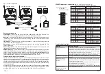
Transmitter and receiver connections
The transmitter and receiver can be connected in many different ways, depending on the
type of equipment providing the AV source, and on other equipment in use with the
remote location TV. This leaflet provides general guidance only. You may find it helpful to
refer to the instructions for the accompanying AV equipment.
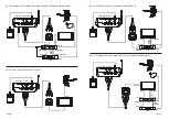
Fig.2a
shows the basic transmitter connections. This configuration is appropriate where
the AV source is a single item of equipment such as a camera, camcorder or VCR. In the
last case the connection to the local TV must be made with an RF (aerial) cable.
Fig.2b
shows how more than one item of source equipment can be connected. The principle
is that the SCART lead that would usually go to the main TV is diverted to the transmitter,
and an RF (aerial lead) connection is used for the main TV. Source selection can be made
from the remote location, provided that both items of source equipment are IR controlled.
Digital source equipment may need to be configured to provide a composite video output,
rather than RGB, for this set-up to work.
Fig.3a
shows the basic receiver connections. The aerial and its downlead should be omitted
in monitoring applications where off-air TV is not required.
Fig.3b
shows how the receiver can be added to a remote location installation with a TV
and dual-SCART VCR.
Fig.3c
shows a VCR and digital satellite receiver in use with a TV which has two or more
SCART connectors. This set-up is recommended where the proWSS1 system is being
used for baby or security monitoring on the main TV. (Best picture quality from a digital
receiver or DVD player will usually be obtained by connecting the receiver or DVD to
SCART input 1 of the TV and, if necessary, configuring it to provide RGB output. The
proWSS1 receiver should be connected to SCART input 2 or 3.)
Phono connections
Equipment with phono connectors (also known as RCA or Cinch) can be connected to
the transmitter or receiver simply by omitting the SCART adapter(s) shown in
Figs.2
and
3
. Plug the proWSS1 cable directly into the equipment, ensuring that each plug is inserted
into the matching coloured socket yellow for video, red for the right audio channel and
white for the left audio channel.
Remote control emitters
Position the emitter(s) on or near the front(s) of AV source (or ancillary) equipment to be
controlled from the remote location. It may be necessary to experiment with the exact
position of the emitter(s) to obtain reliable remote control operation. When suitable
positions have been found, secure the emitters with the self-adhesive pads.
If only one emitter is used, tuck the other one away out-of-sight behind the equipment.
Do not cut off the unused emitter as this will stop the remote control system working.
Power units
The power units supplied are for use with standard UK (BS 1363) mains socket-outlets
only. Before connecting this equipment to the mains supply, read the safety instructions
on page 8.
To install, connect the lead from the power unit into the socket marked 9V DC on the
back of the transmitter or receiver, then plug the power unit into a suitably located mains
socket outlet and switch on.
Disconnect the power units from the mains whenever the equipment is to remain unused
for long periods of time.
Operation selecting a channel
The transmitter and receiver operate on one of four frequency channels, 1 - 4, indicated
by LEDs on the units. Channel 1 is selected by default at switch-on and will be OK in most
cases. If picture interference is experienced, experiment with use of the other channels in
turn and select the channel which gives the best results. To select a channel, press the
CHANNEL button repeatedly until the appropriate LED lights.
The transmitter and receiver must both be set to the same channel, otherwise no signal
will be received. Other than for channel 1 it is necessary to re-select the desired operating
channel when switching the units back on, or after a power cut.
Avoiding interference
To avoid causing interference to other 2.4 GHz wireless products, the transmitter should
be switched off when not in use. This will also reduce the risk of interference with normal
(local) operation of remote controls on the A/V source equipment.
l
e
v
e
l
t
u
p
t
u
o
/
t
u
p
n
i
o
e
d
i
V
5
7
l
a
n
r
e
t
n
i(
p
-
p
V
1
Ω
)
n
o
it
a
n
i
m
r
e
t
s
l
e
v
e
l
t
u
p
t
u
o
/
t
u
p
n
i
o
i
d
u
A
y
l
e
t
a
m
i
x
o
r
p
p
a
S
M
R
V
m
0
5
3
)
V
A
(
d
n
a
b
y
c
n
e
u
q
e
r
f
n
o
i
s
s
i
m
s
n
a
r
T
s
l
e
n
n
a
h
c
r
u
o
f
f
o
e
c
i
o
h
c
,
z
H
G
3
8
4
.
2
..
0
0
4
.
2
)
V
A
(
h
t
d
i
w
d
n
a
b
n
o
i
s
s
i
m
s
n
a
r
T
M
F
:
e
p
y
t
n
o
it
a
l
u
d
o
m
,
y
l
e
t
a
m
i
x
o
r
p
p
a
z
H
M
8
1
)
V
A
(
l
e
v
e
l
r
e
w
o
p
r
e
tt
i
m
s
n
a
r
T
)
W
µ
0
0
1
~
(
y
l
e
t
a
m
i
x
o
r
p
p
a
m
B
d
0
1
-
)
C
R
(
y
c
n
e
u
q
e
r
f
n
o
i
s
s
i
m
s
n
a
r
T
z
H
M
2
9
.
3
3
4
e
g
n
a
r
g
n
it
a
r
e
p
O
s
n
o
it
i
d
n
o
c
t
h
g
i
s
-
f
o
-
e
n
il
r
a
e
l
c
r
e
d
n
u
,
m
u
m
i
x
a
m
s
e
r
t
e
m
0
0
1
&
r
e
t
t
i
m
s
n
a
r
t
o
t
o
t
y
l
p
p
u
s
r
e
w
o
P
s
ti
n
u
r
e
v
i
e
c
e
r
d
e
il
p
p
u
s
,
y
l
e
t
a
m
i
x
o
r
p
p
a
A
m
0
0
3
t
a
)
d
e
t
a
l
u
g
e
r
n
u
(
C
D
V
9
s
ti
n
u
r
e
w
o
p
s
n
i
a
m
n
i
-
g
u
l
p
h
ti
w
e
c
n
a
il
p
m
o
c
s
d
r
a
d
n
a
t
S
;
3
-
9
8
4
1
0
3
N
E
,
1
-
9
8
4
1
0
3
N
E
:
C
M
E
;
0
5
9
0
6
N
E
:
y
t
e
f
a
S
)t
p
m
e
x
e
e
c
n
e
c
il
(
0
4
4
0
0
3
N
E
,
3
-
0
2
2
0
0
3
N
E
:
o
i
d
a
r
Technical data
Fig.2a - Basic transmitter connections.
proWSS1 transmitter
to output SCART
connector
unused IR
emitter
AV source equipment
Note: other connections
required to the AV source
are not shown in this
diagram


