background image

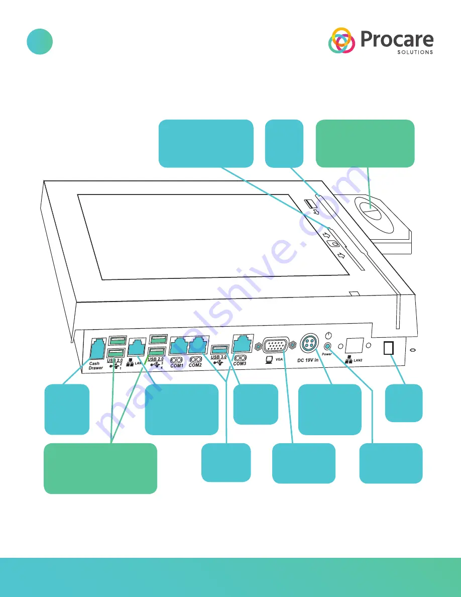
Cash 

drawer 

jack

(Not used)

LAN port 

(Connect to your 

4 USB 2.0 ports

(Use one port for fingerprint

reader. May also connect

an external CD drive.)

network cable– 

not supplied*)

3 COM 

ports 

(Not used)

External 

monitor port

(Not used)

Power 

on/off 

push-button

Card 

swipe 

slot

EMV chip card slot

(See article KB0370 at 

ProcareSupport.com)

USB 3.0 

port

(Not used)

Power cable 

connection

(Connect to 

power brick)

Cord 

holder

clip

Fingerprint

reader 

(Cable connects to 

USB 2.0 port below) 

PORTS & CONNECTIONS

2

Procare Touch 

Diagram

800.338.3884  •  procaresoftware.com

*We recommend you connect the LAN port to a network cable. 

However, you may use the built-in wireless (Wi-fi) capability.

Copyright 2020 Procare Software, All rights reserved

Summary of Contents for Touch Computer

Page 1: ...800 338 3884 procaresoftware com 7 14 16 Procare Touch Computer Installation Instructions Copyright 2020 Procare Software All rights reserved...

Page 2: ...THAT WHAT S NEXT See bottom of page 6 for your next steps UNPACK CONFIRM CONTENTS Included with your shipment 1 Procare Touch computer 1 Power cord connects to power brick 1 Power brick power supply c...

Page 3: ...ipe slot EMV chip card slot See article KB0370 at ProcareSupport com USB 3 0 port Not used Power cable connection Connect to power brick Cord holder clip Fingerprint reader Cable connects to USB 2 0 p...

Page 4: ...rticle KB0901 At your Procare Touch computer 2 Make sure the Procare Touch Computer is connected to your network so it has access to the main computer You may need assistance from a local computer tec...

Page 5: ...4 zip tie M4 0 7 x 8mm pan head machine screws 1 1 1 1 1 1 2 8 4 Your Procare Touch may be mounted in 3 different ways 1 Angled on wall see 5a 2 Flat on wall see 5b 3 Desktop countertop see 5c UNIVERS...

Page 6: ...rd guard over the cords and align with the holes on the mount plate Secure the cord guard by installing two screws on the back side of the mount plate Lift the PC mount plate as shown Insert the tabs...

Page 7: ...screws on the front through the access holes in the cord guard A magnetic tip screwdriver may be helpful Lift the PC mount plate as shown Insert the tabs into the slots at the top of the base mount at...

Page 8: ...unt plate as you see above Be sure the tabs are pointed up Install screws in the 4 positions noted 1 3 2 4 6 5 C A D E 58 50 45 B Insert the tabs from both studded Part D and perforated Part E adjustm...

Page 9: ...s much power cord as needed on top of the power brick hold in place while securing tightening the two zip ties 1 You may choose to snip off any excess zip tie after tightening Warning Do not cut any w...

Reviews: