background image

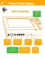
Optional Power Brick Installation

6

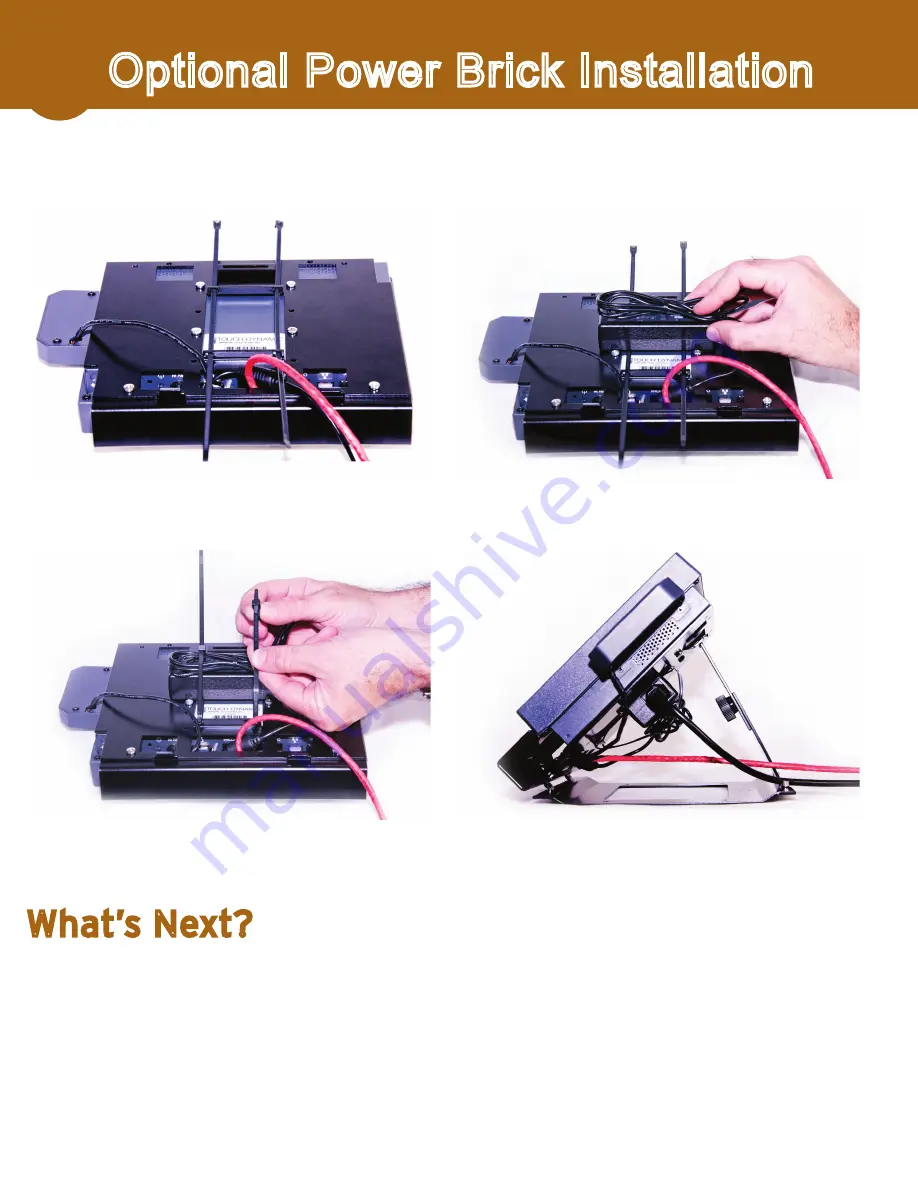
With PC face down on a padded/protected surface, insert the (2) 

14” zip ties through the holes provided in the tabs as shown. 

Place power brick between the two tabs. 

Bundle as much power cord as needed on top of the Power Brick – 

hold in place while securing/tightening the two zip ties. 

You may choose to snip off any excess Zip-Tie after tightening.

Warning: Do not cut any wiring/cables. 

1

2

3

4

The mounting bracket may stow the power brick and cord for a cleaner installation. This 

works with an angled wall or desktop mount, but is not compatible with a flat wall mount.

1. 

Choose settings for the 

Check In Options

 screen (article KB0127).

2. 

Generate 

Temporary Registration Numbers

 for each parent or pickup person (article KB0171).

3. 

Each person will then 

Register for Check In

 at the Procare Touch computer (article KB0227).

4. 

Start 

Checking In

 (article KB0228).

What’s Next?

Search ProcareSupport.com for the following articles:

Summary of Contents for Touch 8"

Page 1: ...Installation Instructions 02072012...

Page 2: ...tional Included with your shipment 1 Procare Touch computer 1 Power cord connects to power brick 1 Power brick power supply connects to computer 1 Box with mounting hardware details page 4 2 Pigtail R...

Page 3: ...CD drive Ethernet port Connect to your network cable not supplied 4 COM ports Use only with supplied RJ45 pigtail to connect optional Door Controller External Display port Not used Power cable connec...

Page 4: ...ne so install Procare on your main computer server choosing a Full or Advanced install Search ProcareSupport com for article KB0901 2 Install the latest Procare online update at the main computer From...

Page 5: ...D Studded Adjustment Plate 1 E Perforated Adjustment Plate 1 F Tension Knob 1 G 14 Zip Tie 2 H M4 0 7 X 8mm Pan Head Machine Screws 8 C A H B D E F G Universal Mount Parts List Your Procare Touch may...

Page 6: ...Mount securely fastened to the wall fasteners not included Lift the PC Mount Plate as shown Insert the TABS into the slots at the top of the Base Mount attached to the wall Once both TABS are fully i...

Page 7: ...all two screws on the front through the access holes in the Cord Guard A magnetic tip screwdriver may be helpful Place the Mount Plate as you see above Be sure the TABS are pointed up Install screws i...

Page 8: ...u may need assistance Holding the plates firmly attach the Tension Knob and tighten The Procare Touch Mount should now be tight and firm PRESS FIRMLY Place the PC face down on a protected padded surfa...

Page 9: ...ening Warning Do not cut any wiring cables 1 2 3 4 The mounting bracket may stow the power brick and cord for a cleaner installation This works with an angled wall or desktop mount but is not compatib...

Reviews: