background image

GIMBAL CONTROL ON MULTICOPTER


NOTE: In single mode, the camera and copter operations are conducted all by one 

person. While in team mode, operations are conducted separately: The photographer is 

in charge of the camera operation and the pilot is in charge of the copter operation. In 

the following we will set single mode as an example. If the user wants to operate in team 

mode, please refer to the instruction manual. 

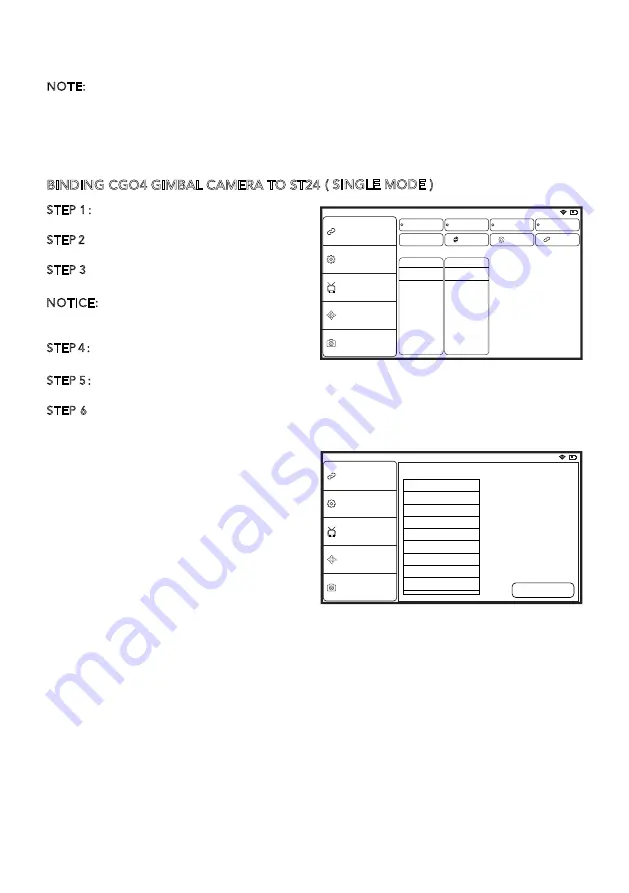
BINDING CGO4 GIMBAL CAMERA TO ST24

STEP 1

Turn on ST24 and tap FPV (First 

Person View) on the main screen.
STEP 2

Select system setting when entered 

First Person View mode.
STEP 3

Select  the  corresponding  camera 

SSID under “Bind” page.
NOTICE: Refresh the list manually so that the 

target camera model can be found on the 

screen. 
STEP 4

Tap “Bind” and enter the 

password:1234567890. 
STEP 5

When the Bind process has been completed, tap “Camera Select” and select the 

camera type “CGO4”.
STEP 6

ST24 is able to create its own Wi-Fi network that streams a real-time view from the 

camera.

Welcome, Pilot

9:43:31 pm

Bind

Bind

RC

Refresh

Model

SR24S_22622

YUNEEC_819203

Camera

ST24

FPV

Aircraft

FPV+DA58

Reset

FPV+ADA58

Other Settings

Mode Select

Hardware Monitor

Camera Select

In the default system settings of ST24, K5 

takes control of the Pitch direction while K1 

takes control of the Yaw direction. If K5 

moves upward, the camera lens will trim 

itself up. If K5 moves downward, the 

camera lens will trim itself down. If K1 is 

rotated to the right, the camera lens will 

trim itself to the right. If K1 is rotated to the 

left, the camera lens will trim itself to the 

left.

Welcome, Pilot

9:43:31 pm

Bind

Other Settings

Mode Select

Hardware Monitor

Camera Select

Choose a camera:

Name:   C-GO4

Type:   lumix

Select

C-GO1

Sony_A7

Canon_5D3

V18

Panasonic_GH3/GH4

C-GO2

C-GO3

C-GO3-Pro

C-GO4

GIMBAL CONTROL ON PROACTION™

There are two modes to control the gimbal through ProAction™: Follow Mode and Global 

Mode.

Switch on the ProAction™ on a flat and stable surface. Do not move, sway or shake the 

ProAction™ during initialization. After initialization, the gimbal will boot up normally in 

either Follow or Global Mode, depending on user settings on the left-hand switches of the 

ProAction™. Once the gimbal is on, it begins an automatic self-check by rotating about 

the yaw axis. At this time, the power indicator will be on as well. At the same time the 

control status LED will blink green and blue alternately.   

( SINGLE MODE )

Summary of Contents for CG04

Page 1: ...V12242015...

Page 2: ...duct correctly can result in damage to the product property and or cause serious injury WARNING This is a sophisticated consumer product It must be operated with caution and common sense and requires...

Page 3: ...for professional users who require ultra high aerial imaging quality and resolution The dream of a flight adjustable 3 axis stabilized m4 3 inch sensor aerial capturing system is now a reality CGO4 i...

Page 4: ...for ProAction between 90 to 30 Yaw 360 limitless Input Operating Voltage 24V Mechanical Range Pitch between 120 and 45 Roll between 40 and 40 Yaw 360 limitless Maximum Control Speed Pitch 30 s Yaw 30...

Page 5: ...g NOTICE When recording 4K motion pictures use a card rated as UHS Speed Class 3 CAUTION the use of adapter card is not allowed SD STEP 1 Install the CGO4 rubber dampers 4 pcs into the four outermost...

Page 6: ...all the ProAction battery and engage the connector properly STEP 4 Erect the phone holder and install the mobile phone into it and then you can make Wi Fi connection between CG04 gimbal camera and mob...

Page 7: ...ED blinking blue CGO4 Wi Fi malfunction LED blinking red CGO4 GIMBAL Firmware update in progress LED blinking blue Firmware update succeeds LED blinking green Firmware update Fails LED blinking red Po...

Page 8: ...58 Reset FPV ADA58 Other Settings Mode Select Hardware Monitor Camera Select In the default system settings of ST24 K5 takes control of the Pitch direction while K1 takes control of the Yaw direction...

Page 9: ...imbal Control Stick moves downward the camera lens will trim itself down If the Gimbal Control Stick turns right the camera lens will trim itself to the right If the Gimbal Control Stick turns left th...

Page 10: ...ure the roll angle is less than 40 degree PHOTO TAKING AND VIDEO RECORDING TO TAKE PHOTOS Press the button located on the left side of ST24 You ll hear an audible shutter sound from ST24 and it will t...

Page 11: ...on the top right corner of the screen CAUTION If the video is being recorded repress the video recording button to end the process before powering off the gimbal or the video is unable to be saved WAR...

Page 12: ...These limits are designed to provide reasonable protection against harmful interference in a residential installation This equip ment generates uses and can radiate radio frequency energy and if not...

Page 13: ...environment Cet quipementrespecte les limitesd exposition aux rayonnements IC d finies pour un environnement non contr l IC RADIATION EXPOSURE STATEMENT FOR CANADA YUNEEC EU 24568 Kaltenkirchen German...

Reviews: