

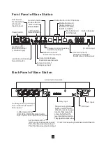
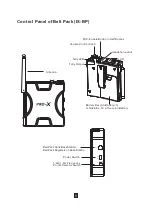


Front Panel of Base Station
Back Panel of Base Station
3
SPEAKER
POWER
MIC
VOX
2W/4W
VOX
AUX
VOL
MIN
MAX
IN
IN
INTERCOM LEVEL
AUX LEVEL
OUT
OUT
LEVEL
LEVEL
5V
DC OUT
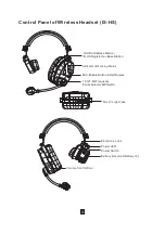
HEAD
PHONE
ALL
1
2
3
4
MUTE
MIC
Power Switch
XLR Socket for
Microphone Input
(1st Audio Input)
HEADPHONE/SPEAKER
Selector Switch
2-Wire/4-Wire
Selector Button
Voice Control
Enable Button
Auxiliary Audio
Enable Button
Volume Control of
Microphone Input
Voice Control Enable
Electrical Level Adjustor
Volume Control of
Intercom Output/Input
Volume Control of Auxiliary
Audio Output/Input
Enable Button of All Channels
Enable Button and
Status Indicator of
IS-HS1 to IS-HS4/
IS-BP1 to IS-BP4
Mute Button for
All Channels
Volume Control of
Headphone/Speaker
from Minimum to Maximum
Built-in Speaker
5V
DC Output
V
H
V
H
2 WIRE
INPUT
OUTPUT
AUX AUDIO
INTERCOM
Red LED
GND
CH
1 2 3 4 1 2 3 4
NC NC
Green LED
TALLY
MODE
H
L
FREQ
1
.
8G
1
.
9G
Red LED
GND
CH
1 2 3 4 1 2 3 4
NC NC
Green LED
AC Input
DC Input
Tally Active-high and
Active-low DIP Switch
When the lever is at upper
location, Tally signal is in
active-high. When the
lever is at bottom location,
Tally signal is in active-low.
1.8G/1.9G Frequency
Points Selector DIP Switch
Tally Input
4-Wire Intercom Port
(RJ11 and XLR-4F parallel inside)
Pin1, Pin4: Balanced Audio Input;
Pin2, Pin3: Balanced Audio Output
XLR-4F
RJ11
2-Wire Intercom Port
(XLR-3F and XLR-3M parallel inside)
Pin1: Public; Pin2: Null; Pin3: Audio
XLR-3M
XLR-3F
Auxiliary Audio Input/Output
Pin1: Public; Pin2: Audio”+”;
Pin3: Audio”-”
Antenna Connectors
XLR Socket
for Headphone
(2nd Audio
Input/Output)
Summary of Contents for XW-IS4
Page 1: ...XW IS4 XW IS4 Intercom System Intercom System ...
Page 15: ......
Page 16: ......
Page 17: ......
Page 18: ......
Page 19: ......
Page 20: ......
Page 21: ......
Page 22: ......
Page 23: ......
Page 24: ......
Page 25: ......
Page 26: ......
Page 27: ......
Page 28: ......
Page 29: ......
Page 30: ......