


13
9.
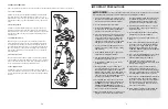
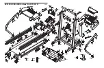
Make sure that all parts are properly tightened before you use the treadmill.
Note: Extra hardware may
be included. Keep the included hex keys in a secure place. The large hex key is used to adjust the walking
belt (see page 16). To protect the floor or carpet, place a mat under the treadmill.
47
42
44
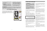
7. Insert the excess Wire Harness (42) into the large hole in
the side of the Right Handrail (72).
Securely tighten the
nylon ties on the bottom of the Console Base (47) to
prevent the Wire Harness from slipping.
Then, cut off
the ends of the nylon ties.
Route the Wire Harness (42) through the indicated open-
ing in the Console Base (47). Attach the Wire Cover (44)
to the Console Base with a Silver Ground Screw (75).
Tighten two 3/4” Screws (61) into the Console Base (47).
7
61
72
75
Ties
Opening
47
Ties
72
6
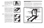
6. Place the Console Base (47) on the Right Handrail (72)
and the Left Handrail (not shown). Attach the Console
Base with four 3/4” Screws (61) (only two Screws are
shown).
Do not overtighten the Screws.
Insert the Wire Harness (42) through the two indicated
nylon ties on the Console Base (47). Next,
touch the
Right Handrail (72) to discharge any static.
Refer to
drawing 6c. Find the connector on the end of the Wire
Harness (42). Insert the connector into the red socket be-
neath the Console (43).
The connector should slide eas-
ily into the socket and snap into place.
If the connector
does not slide easily and snap into place, turn the connec-
tor and then insert it.
Make sure that the connector and wires appear as
shown in drawing 6a.
IF THE CONNECTOR IS NOT IN-
SERTED PROPERLY, THE CONSOLE MAY BE DAM-
AGED WHEN THE POWER IS TURNED ON.
42
43
61
42
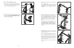
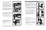
HOW TO FOLD AND MOVE THE TREADMILL
HOW TO FOLD THE TREADMILL FOR STORAGE
Before folding the treadmill, adjust the incline to the
lowest position. If this is not done, the treadmill may be per-
manently damaged. Next, unplug the power cord. CAUTION:
You must be able to safely lift 20 kg (45 lbs.) to raise, lower,
or move the treadmill.
1. Hold the treadmill with your hands in the locations shown at the
right.
To decrease the possibility of injury, bend your legs
and keep your back straight. As you raise the treadmill,
make sure to lift with your legs rather than your back.
Raise the treadmill about halfway to the vertical position.
2. Move your right hand to the position shown and hold the
treadmill firmly. Using your left hand, pull the latch knob to
the left and hold it. Raise the treadmill until the frame is past
the latch pin. Slowly release the latch knob.
Make sure that
the frame is securely held by the latch pin.
To protect the floor or carpet from damage, place a mat
under the treadmill. Keep the treadmill out of
direct sunlight. Do not leave the treadmill in the storage
position in temperatures above 30° C (85° F).
HOW TO MOVE THE TREADMILL
Before moving the treadmill, convert the treadmill to the storage
position as described above.
Make sure that the frame is se-
curely held by the latch pin.
1. Hold the upper ends of the handrails. Place one foot on the
base as shown.
2. Tilt the treadmill back until it rolls freely on the front wheels.
Carefully move the treadmill to the desired location.
To re-
duce the risk of injury, use extreme caution whilst mov-
ing the treadmill. Do not move the treadmill over an un-
even surface.
3. Place one foot on the base, and carefully lower the treadmill
until it is resting in the storage position.
Engaged
Frame
Latch
Knob
Latch Pin
Base
Front Wheels
6a
8. Lower the Handrails (not shown) to the floor.
Make sure
that the Frame (86) is centered between the
Handrails. Firmly tighten the two lower 3” Bolts (70).
Firmly tighten the two upper 3” Bolts.
Firmly tighten the bolts and screws used in steps 3,
4, and 6.
Raise the Handrails to the vertical position.
70
69
70
86
8
8


