Pro-Form 360 P PETL3013.7 User Manual Download Page 5

16

5

Congratulations for selecting the new PROFORM

®

360

P treadmill. The 360 P treadmill combines advanced
technology with innovative design to help you get the
most from your exercise in the convenience and pri-
vacy of your home. And when you’re not exercising, the
unique 360 P treadmill can be folded up, requiring less
than half the floor space of other treadmills.

For your benefit, read this manual carefully before
using the treadmill

. If you have questions after read-

ing this manual, please call our Customer Service
Department at 

08457 089 009

. To help us assist you,

please note the product model number and serial num-
ber before calling. The model number of the treadmill
is PETL3013.7. The serial number can be found on a
decal attached to the treadmill (see the front cover of
this manual for the location). 

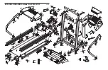
Before reading further, please familiarise yourself with
the parts that are labelled in the drawing below.
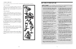
BEFORE YOU BEGIN

Handrail

Upright

Storage Latch

Key/Clip

Circuit Breaker

Walking Belt

Cushioned Walking Platform

for maximum exercise comfort

Foot Rail

RIGHT SIDE

Rear Roller  
Adjustment Bolts

Console

Bookrack

Water Bottle Holder

(Bottle not included) 

On/Off Switch

BACK

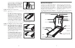
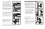
Locate the Reed Switch (10) and the Magnet (18) on
the left side of the Pulley (17). Turn the Pulley until the
Magnet is aligned with the Reed Switch. 

Make sure

that the gap between the Magnet and the Reed
Switch is about 3 mm (1/8 in.).

If necessary, loosen

the Screw (26) and move the Reed Switch slightly.
Retighten the Screw. Re-attach the Hood (not shown),
and run the treadmill for a few minutes to check for a
correct speed reading.

PROBLEM: The walking belt slows when walked on

SOLUTION:

a. If an extension cord is needed, use only a 3-conductor, 1mm

2

(14-gauge) cord that is no longer

than 1.5 m (5 ft.).

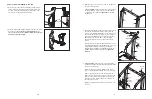
b. If the walking belt is overtightened, treadmill perfor-

mance may decrease and the walking belt may be-
come damaged. Remove the key and 

UNPLUG THE

POWER CORD

. Using the hex key, turn both rear

roller adjustment bolts counterclockwise, 1/4 of a turn.
When the walking belt is properly tightened, you
should be able to lift each side of the walking belt
8–10cm (3-4 in.) off the walking platform. Be careful to
keep the walking belt centred. Plug in the power cord,
insert the key, and run the treadmill for a few minutes.
Repeat until the walking belt is properly tightened.

c. If the walking belt still slows when walked on, call our Customer Service Department.

PROBLEM: The walking belt is off-centre or slips when walked on

SOLUTION:

a. If the walking belt is off-centre, remove the key and

UNPLUG THE POWER CORD

.

If the walking belt

has shifted to the left,

use the hex key to turn the left

rear roller bolt clockwise 1/2 of a turn; 

if the walking

belt has shifted to the right,

turn the left rear roller

bolt counterclockwise 1/2 of a turn. Be careful not to
overtighten the walking belt. Plug in the power cord,
insert the key, and run the treadmill for a few minutes.
Repeat until the walking belt is centred. 

b. If the walking belt slips when walked on, first remove

the key and 

UNPLUG THE POWER CORD

. Using

the hex key, turn both rear roller bolts clockwise, 1/4
of a turn. When the walking belt is correctly tightened,
you should be able to lift each side of the walking belt
8–10cm (3–4 in.) off the walking platform. Be careful
to keep the walking belt centred. Plug in the power
cord, insert the key, and walk on the treadmill for a
few minutes. Repeat until the walking belt is properly
tightened.

b

a

Rear Roller Adjustment Bolts

8–10 cm

b

18

10

26

Top

View

3 mm

17

Summary of Contents for 360 P PETL3013.7

Page 1: ... you please be prepared to give the following information The MODEL NUMBER of the product PETL3013 7 The NAME of the product PROFORM 360 P treadmill The SERIAL NUMBER of the product see the front cover of this manual The KEY NUMBER and DESCRIPTION of the desired part s see the PART LIST and the EXPLODED DRAW ING in the centre of this manual Class H Fitness Product QUESTIONS As a manufacturer we ar...

Page 2: ... AND ADJUSTMENT 9 HOW TO FOLD AND MOVE THE TREADMILL 13 TROUBLESHOOTING 15 CONDITIONING GUIDELINES 17 ORDERING REPLACEMENT PARTS Back Cover Note An EXPLODED DRAWING and a PART LIST are attached in the centre of this manual 19 PROFORM is a registered trademark of ICON IP Inc 2 NOTES ...

Page 3: ...e treadmill 17 The treadmill is capable of high speeds Adjust the speed in small increments to avoid sudden jumps in speed 18 The pulse sensor is not a medical device Various factors including your movement may affect the accuracy of heart rate readings The sensor is intended only as an exercise aid in determining heart rate trends in general 19 Never leave the treadmill unattended whilst it is ru...

Page 4: ...ity level for a sustained period of time During the first few minutes of exercise your body uses easily accessible carbohydrate calories for en ergy Only after the first few minutes does your body begin to use stored fat calories for energy If your goal is to burn fat adjust the speed and incline of the tread mill until your heart rate is near the lowest number in your training zone For maximum fa...

Page 5: ...LUTION a If an extension cord is needed use only a 3 conductor 1mm2 14 gauge cord that is no longer than 1 5 m 5 ft b If the walking belt is overtightened treadmill perfor mance may decrease and the walking belt may be come damaged Remove the key and UNPLUG THE POWER CORD Using the hex key turn both rear roller adjustment bolts counterclockwise 1 4 of a turn When the walking belt is properly tight...

Page 6: ...with Star Washers 63 into the bottom of the Base and the lower end of the Right Upright With the help of a second person tip the treadmill onto its other side Attach the Left Upright 25 as described above Note There is not a wire harness on the left side Attach the other Wheel not shown to the Base 69 as described in step 1 58 58 57 65 69 58 65 86 64 66 1 42 Holes Bracket 29 69 25 2a 45 29 25 TROU...

Page 7: ...o not tighten the Crossbar Screws yet 29 39 25 39 40 3 5 Open part bag C Attach the end of the ground wire to the small hole in the side of the Right Handrail 72 with a Silver Ground Screw 75 Attach the Storage Latch 36 with the Latch Spacer 116 to the Left Upright 25 with two 3 4 Screws 61 Remove the Latch Knob 30 from the Latch Pin 35 Make sure that the Latch Pin Collar 33 and the Spring 32 are ...

Page 8: ... position If this is not done the treadmill may be per manently damaged Next unplug the power cord CAUTION You must be able to safely lift 20 kg 45 lbs to raise lower or move the treadmill 1 Hold the treadmill with your hands in the locations shown at the right To decrease the possibility of injury bend your legs and keep your back straight As you raise the treadmill make sure to lift with your le...

Page 9: ...ded power cord See drawing 1 Plug the indicated end of the power cord into the socket on the treadmill Lift the tab on the ferrite box and clamp the ferrite box around the power cord Fasten the included plastic tie just behind the ferrite box and cut off the excess plastic tie The plastic tie will prevent the ferrite box from sliding along the power cord See drawing 2 Press the pins on the power c...

Page 10: ...e stand on the foot rails and place your thumb on the pulse sensor Do not press too hard or the circu lation in your thumb will be restricted and your pulse will not be detected After a few seconds the heart shaped indicator in the Fat Calories Calories Pulse display will begin to flash one or two dashes will appear and then your heart rate will be shown Hold your thumb on the pulse sensor for abo...

Page 11: ... 1 Bookrack 47 1 Console Base 48 1 Lift Frame Ground Wire 49 2 Console Screw 50 1 Key Clip 51 1 Incline Motor 52 1 Incline Stop Bracket 53 1 Incline Motor Bolt Top 54 2 Lift Frame Bolt 55 2 Lift Frame Nut 56 1 Motor Controller Wire 57 2 Base Pad 58 4 1 Tek Screw 59 1 Controller 60 1 Lift Frame 61 18 3 4 Screw 62 2 Warning Decal 63 4 Star Washer 64 2 2 Bolt 65 2 Base Endcap 66 2 Wheel 67 1 Motor Sl...

Page 12: ... 62 69 54 55 54 57 58 72 37 76 73 58 57 51 37 38 39 37 38 37 38 39 37 38 40 61 62 64 50 79 90 58 89 68 100 42 15 75 61 101 11 55 56 85 84 84 85 71 73 61 108 86 15 65 111 111 13 66 78 1 61 61 25 29 45 45 61 70 63 63 70 61 36 79 8 114 87 113 61 110 5 7 112 109 58 58 42 75 37 76 88 115 22 22 22 61 22 67 38 79 48 3 4 6 9 103 20 104 105 41 41 116 107 27 106 26 59 26 26 24 26 EXPLODED DRAWING Model No P...

Reviews: