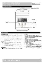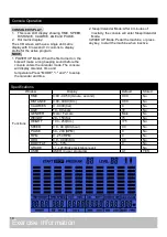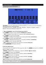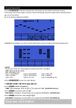
Assembly Instructions
A.
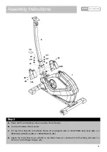
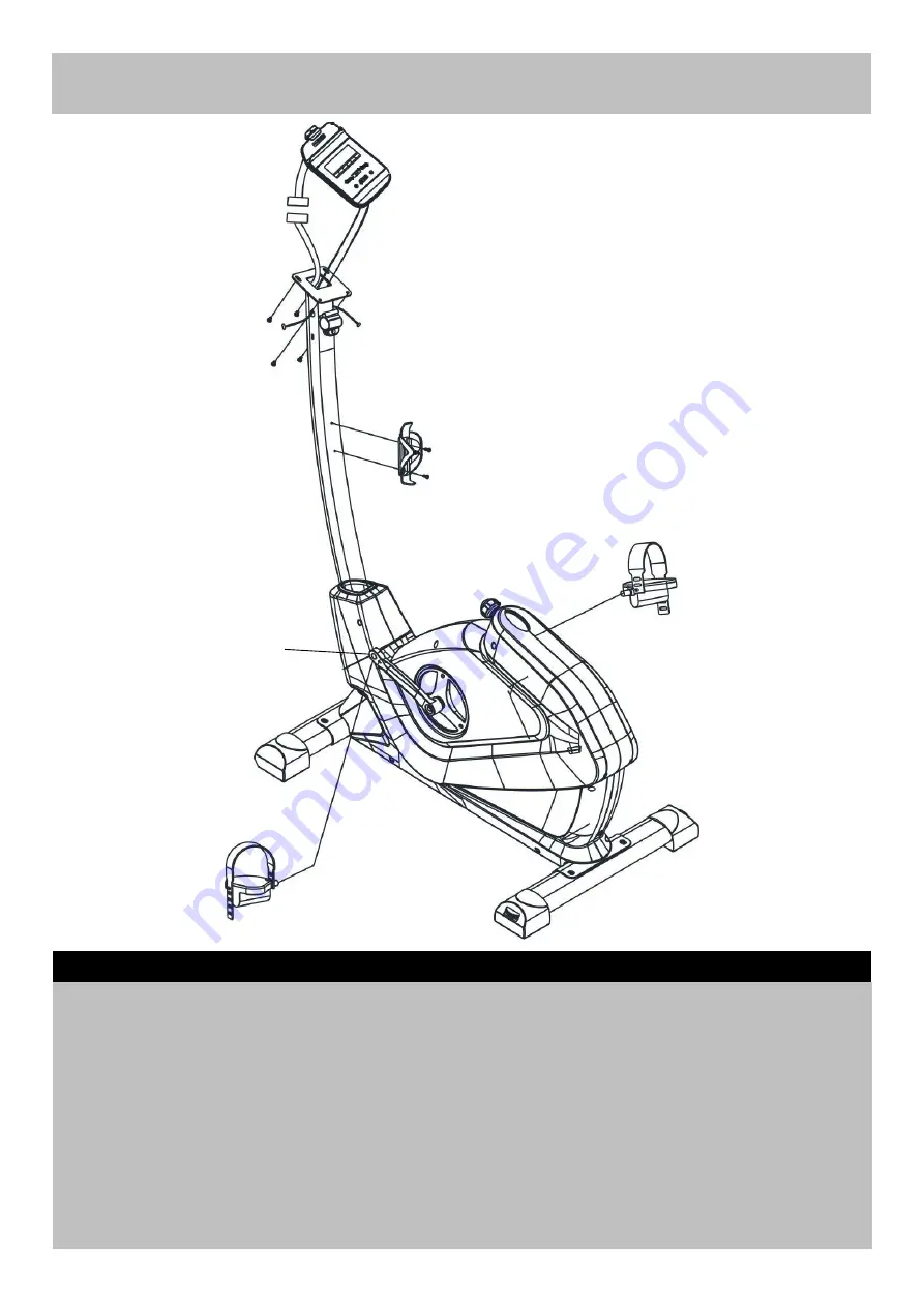
Connect the Pedals (12 L&R) to Cranks (46 L&R) as shown.
Note: For the two foot pedals marked "L" and "R". Fasten the left pedal by turning anti-clockwise and
fasten the right pedal by turning clockwise. Attach the pedal straps to the pedals as shown in the
diagram, the tension for pedal strap is adjustable.
B.
Fix the Bottle Holder (
16
) to the Front Post (
6
) with2 x ST4.8 x 15mm Philips Screw (75).
C.
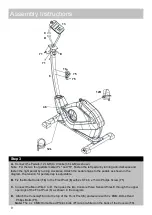
Connect the Main Wire C to D, then pass the two Console Pulse Sensor Wires E through the upper
openings of the Front Post (6) as shown in the diagram.
D.
Attach the Console(
13
) onto the top of the Front Post (
6
) and secure with 4 x 8MM Dome Head
Philips Bolts (
71
).
Note:
The 4 x 8MM Dome Head Philips bolts (
71
) are pre-fitted on the back of the Console (
13
).
Step 3
9
C
D
12R
12L
16
6
75
E
13
71
71
E
75
46
Summary of Contents for 859/8978
Page 30: ...Exploded Parts Diagram 29...


