15
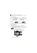
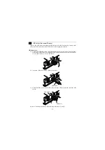
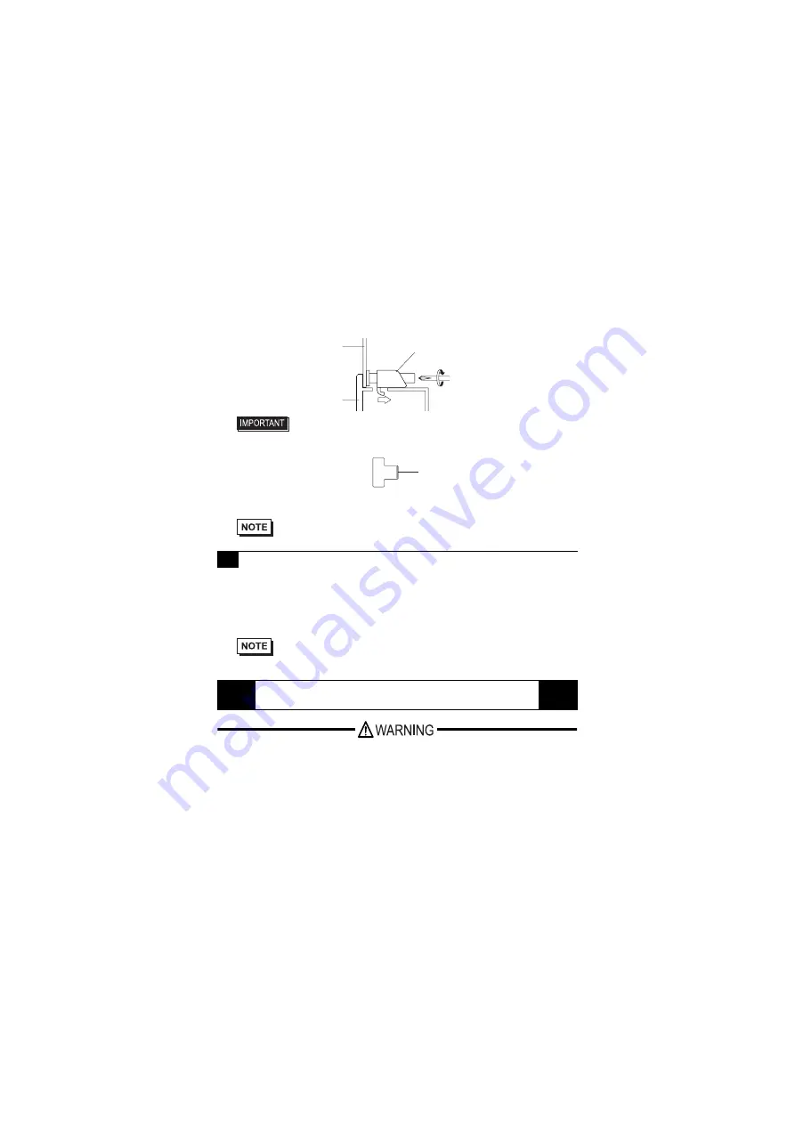
(3) Insert the hook of the installation fastener into the insertion slot of the PS-G unit and
tighten the back of the installation fastener using a screwdriver. For the position of the
insertion slot, refer to the dimension illustration.
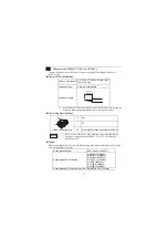
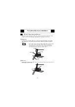
The PS-G unit can be mounted on a stand or wall by attaching a commercially available arm
or wall-mounting adapter to the arm mounting hole (VESA-75 mm [2.95 in.] specification)
on the rear face of the PS-G unit.
Secure the arm or adapter with M4 screws (maximum length: 6 mm [0.24 in.]). The
tightening torque is 0.7 to 0.8 N
•
m. For the attaching procedure, refer to the instruction
manual provided with the arm or wall-mounting adapter.
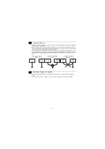
Wiring
•
To avoid an electric shock, prior to connecting the PS-G unit’s power cord terminals to the power
terminal block, confirm that the PS-G unit’s power supply is completely turned OFF, via a
breaker, or similar unit.
•
The PS3600G-T41 unit’s are designed to use AC100 to 240 V input. The PS3600G-T41-24V is
designed to use only DC24 V. Supplying a power voltage other than that specified will damage
the power source and the PS-G unit.
•
When the FG terminal is connected, be sure the wire is grounded.
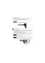
• Be sure to insert installation fasteners in the recessed portion of a
installation fasteners hole. (Refer to the following figure.) If the
fasteners are not correctly attached, the PS-G unit may shift or fall out of
the panel.
• Tightening the screws with too much force can damage the PS-G unit’s
plastic case.
• The torque required to tighten these screws is 0.5 N
•
m.
• The installation fastener’s model number is CA3-ATFALL-01.
3
Mounting a VESA Arm
• If the VESA arm is installed with the PCMCIA card adapter unit (PSG-
PCM00) attached to the PS-G unit, the inclination of the display face
might be limited depends on the form of the VESA arm.
Wiring
Panel
Installation Fastener
PS-G
Insertion Slot Recess


