background image

17

   En

g

lish

Installation

1. Installation Method

Panel type: Weld the stud bolts to the panel, and then tighten the nuts to 
fasten the GP unit to the panel.
Resin boss type: Tighten the screws to attach the GP unit to the bosses of the 
resin boss-molded product.

Standard mount: The GP unit's screen is fixed within the inside of the panel or 
resin boss-molded product.
Flat mount: The GP unit's screen is fixed to the same surface of the panel or 
resin boss-molded product.

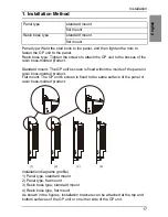
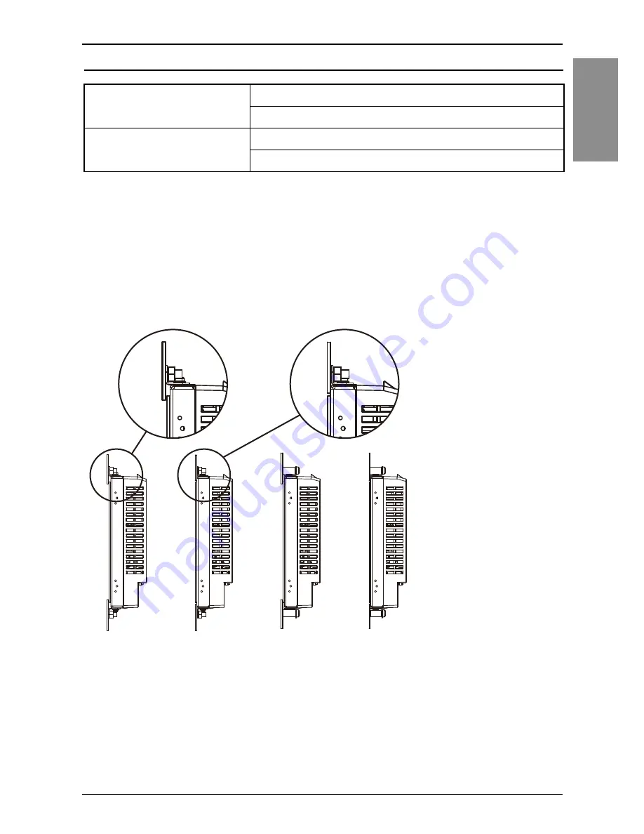
Installation diagrams (profile)
1) Panel type, standard mount
2) Panel type, flat mount
3) Resin boss type, standard mount
4) Resin boss type, flat mount
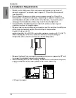
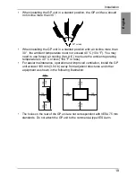
As shown in the figures, installation brackets can be attached at the top and 
bottom surfaces of the GP unit or on either side of the GP unit.

Panel type

standard mount
flat mount

Resin boss type

standard mount
flat mount

(1)

(2)

(3)

(4)

Summary of Contents for PFXGP4301TADR

Page 1: ...GP4000 Series Rear Mount Model Installation Guide...

Page 2: ...401TADR 9 3 PFXGP4501TADR 10 4 PFXGP4601TADR 11 5 LED Indications 12 Interface Serial Interface 14 Installation 1 Installation Method 17 2 Installation Requirements 18 3 Panel Cut Dimensions 20 4 Pane...

Page 3: ...set attached to the top and bottom surfaces of the GP unit 7 GP4000 Series Rear Mount Model Installation Guide this guide 1 8 Warning Caution Information 1 This unit has been carefully packed with sp...

Page 4: ...dware Manual You can download the manual from our website at http www pro face com trans en manual 1001 html Global Code A global code is assigned to every Pro face product as a universal model number...

Page 5: ...er Consumption 10 5 W or less 12 W or less When power is not supplied to external devices 6 5 W or less 8 W or less Backlight is OFF Standby Mode 4 5 W or less 5 W or less Backlight Dimmed Brightness...

Page 6: ...less Power Consumption 17 W or less When power is not supplied to external devices 12 W or less Backlight OFF Standby Mode 7 W or less Backlight Dimmed Brightness 20 8 W or less In Rush Current 30 A...

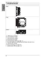
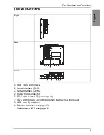
Page 7: ...l Interface COM1 C Serial Interface COM2 D Power Plug Connector E SD Card Access LED see page 13 F SD Card Interface Cover Replacement Battery Insertion Cover G USB mini B Interface H Ethernet Interfa...

Page 8: ...l Interface COM1 C Serial Interface COM2 D Power Plug Connector E SD Card Access LED see page 13 F SD Card Interface Cover Replacement Battery Insertion Cover G USB mini B Interface H Ethernet Interfa...

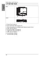
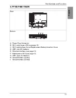
Page 9: ...SD Card Access LED see page 13 C SD Card Interface Cover Replacement Battery Insertion Cover D USB mini B Interface E Ethernet Interface see page 13 F Maintenance LED see page 12 G USB Type A Interfac...

Page 10: ...SD Card Access LED see page 13 C SD Card Interface Cover Replacement Battery Insertion Cover D USB mini B Interface E Ethernet Interface see page 13 F Maintenance LED see page 12 G USB Type A Interfac...

Page 11: ...ns design software so that switches and other controls arranged on the screen do not function when you want the screen to be off even if these controls are accessed with touch operations 1 Failure to...

Page 12: ...D Card is inserted OFF The SD Card is not inserted or is not being accessed Color Indicator Description Green Active Flashing Data transmission is occurring OFF No data transmission Green Link ON Data...

Page 13: ...hat a short circuit loop is not created when you set up the system Connect the 5 SG terminal to remote equipment when the host PLC unit is not isolated Connect the 5 SG terminal to a known reliable gr...

Page 14: ...tion Cable Cover XM2S 0913 manufactured by OMRON Corporation Jack Screw 4 40 UNC XM2Z 0073 manufactured by OMRON Corporation Pin Number RS 232C Signal Name Direction Meaning 1 CD Input Carrier Detect...

Page 15: ...OMRON Corporation Jack Screw 4 40 UNC XM2Z 0073 manufactured by OMRON Corporation Pin Number RS 422 RS 485 Signal Name Direction Meaning 1 RDA Input Receive Data A 2 RDB Input Receive Data B 3 SDA Out...

Page 16: ...of the panel or resin boss molded product Flat mount The GP unit s screen is fixed to the same surface of the panel or resin boss molded product Installation diagrams profile 1 Panel type standard mo...

Page 17: ...is flat in good condition and has no jagged edges Be sure that the surrounding air temperature and the ambient humidity are within their designated ranges Surrounding air temperature 0 to 55 C 32 to 1...

Page 18: ...n A C to ensure the ambient operating temperature is 40 C or less 104 F or less For easier maintenance operation and improved ventilation install the GP unit at least 100 mm 3 94 in away from adjacent...

Page 19: ...ena or boss molds e Center of the display area A B C R Panel Type Resin Boss Type PFXGP4301TADR 118 8 mm 0 5 0 mm 4 68 in 0 02 0 in 90 mm 0 5 0 mm 3 54 in 0 02 0 in 1 6 mm 0 06 in to 3 2 mm 0 13 in SP...

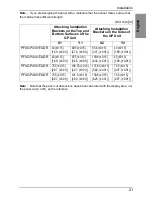
Page 20: ...on Brackets on the Top and Bottom Surfaces of the GP Unit Attaching Installation Brackets on the Sides of the GP Unit X1 Y1 X2 Y2 PFXGP4301TADR 43 0 15 1 69 0 01 69 5 0 15 2 74 0 01 85 6 0 15 3 37 0 0...

Page 21: ...m 5 63 in 0 02 0 in 109 mm 0 5 0 mm 4 29 in 0 02 0 in 1 6 mm 0 06 in SPCC JIS G 3141 or SECC JIS G 3313 1 5 mm 0 06 in SUS304 JIS G 4305 2 mm 0 08 in maximum 1 mm 0 04 in maximum 70 5 mm 0 25 0 mm 2 7...

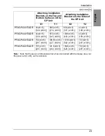
Page 22: ...ching Installation Brackets on the Sides of the GP Unit X1 Y1 X2 Y2 PFXGP4301TADR 43 0 15 1 69 0 01 69 5 0 15 2 74 0 01 85 6 0 15 3 37 0 01 43 0 15 1 69 0 01 PFXGP4401TADR 43 0 15 1 69 0 01 87 5 0 15...

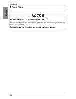
Page 23: ...ation 4 Panel Type NOTICE PANEL UNSTEADY WHEN UNSECURED Keep GP unit stabilized in the panel cut while you are installing or removing the screw fasteners Failure to follow the instruction can result i...

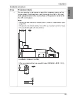
Page 24: ...erpendicular to the rear surface of the panel in order to fix the GP unit in place Note Before you start this work carefully read 3 Panel Cut Dimensions see page 20 Prepare four stud bolts and four nu...

Page 25: ...ing installation brackets on either side of the GP unit Note Be sure to use the included installation gaskets Due to the installation gasket properties do not pull on the installation gaskets while yo...

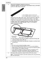
Page 26: ...itions on the sides of the GP unit or if you are installing the GP unit with the flat mount orientation read steps 5 to 7 5 Switching the installation brackets to their positions on the sides of the G...

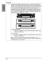
Page 27: ...d flat mount figure B orientations Use a Phillips head screwdriver to fix in place two installation screws per installation bracket The tightening torque is 0 8 N m 7 1 lb in A Standard mount 1 Use tw...

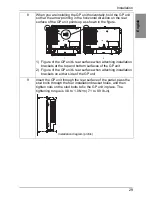
Page 28: ...aching installation brackets at the top and bottom surfaces of the GP unit 2 Figure of the GP unit s rear surface when attaching installation brackets on either side of the GP unit 9 Insert the GP uni...

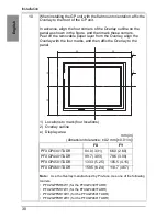
Page 29: ...marks and then affix the Overlay to the panel 1 Locations to mark four locations 2 Overlay outline e Display area Note Use the Overlay manufactured by Pro face Use one of the following models PFXZGPFS...

Page 30: ...8 N m 7 1 lb in of torque when tightening the installation screws For use on a flat surface of a Type 1 Enclosure Attach the Overlay correctly with the installation Do not reuse the Overlay removed o...

Page 31: ...t Do not push the LCD panel strongly When installing the GP unit with the flat mount orientation affix the Overlay to the front of the GP unit Do not drop the GP unit when you remove it from the panel...

Page 32: ...removing the screw fasteners Failure to follow the instruction can result in equipment damage Step Procedure Details 1 Follow the standard mount or flat mount panel cut dimensions to perform sufficien...

Page 33: ...ss max 2 mm 0 08 in Note Before you start this work carefully read 3 Panel Cut Dimensions see page 20 Design the resin plate on the basis of sufficient testing and within your quality assurance range...

Page 34: ...tion brackets at the top and bottom surfaces of the GP unit b Boss when attaching installation brackets on either side of the GP unit Note Be sure to use the included installation gaskets Due to the i...

Page 35: ...es down and then place the GP unit on a clean and level surface 6 Use a Phillips head screwdriver to remove the two installation screws fixing the one installation bracket in place on the top surface...

Page 36: ...installation brackets at the top and bottom surfaces of the GP unit 2 Figure of the GP unit s rear surface when attaching installation brackets on either side of the GP unit 9 Insert the GP unit thro...

Page 37: ...marks and then affix the Overlay to the panel 1 Locations to mark four locations 2 Overlay outline e Display area Note Use the Overlay manufactured by Pro face Use one of the following models PFXZGPFS...

Page 38: ...an 0 8 N m 7 1 lb in of torque when tightening the installation screws For use on a flat surface of a Type 1 Enclosure Attach correctly without a crevice between gaskets and between gasket and the pan...

Page 39: ...the glass of the front of the GP unit Wear gloves when you are installing the GP unit Do not push the LCD panel strongly When installing the GP unit with the flat mount orientation affix the Overlay t...

Page 40: ...fore removing any elements of the system and prior to installing or removing any accessories hardware or cables Remove power before wiring the GP unit s power terminals The DC model uses only 24 Vdc p...

Page 41: ...75 C 167 F Copper conductors only 1 If the conductor s end individual wires are not twisted correctly the end wires may either short against each other or against an electrode Power Cord Diameter 0 75...

Page 42: ...4501TADR PFXGP4601TADR is PFXZCBCNDC2 manufactured by Pro face Items are made by Phoenix Contact Connection Wire 24 Vdc 0 Vdc FG Grounded terminal connected to the panel chassis Recommended Driver SZS...

Page 43: ...he rated voltage and remove the DC24V sticker on the DC power supply connector 3 Remove 10 mm 0 39 in of the vinyl membrane off the ends of the power cord wires 4 If using stranded wire twist the ends...

Page 44: ...ise on the power supply line connect a noise reducing transistor before turning on the power Connect a surge absorber to handle power surges Be sure to ground the surge absorber E1 separately from the...

Page 45: ...the USB cable has been fixed with the USB cable clamp before using the USB interface Remove power before attaching or detaching any connectors to or from the unit Failure to follow these instructions...

Page 46: ...is through the center of the tie loop and that the tie can pass through the head You can substitute the tie provided with PFXZCBCLUSA1 manufactured by Pro face or other commercially available ties wit...

Page 47: ...s I Division 2 wiring methods Substitution of any component may impair suitability for Class I Division 2 Do not disconnect equipment while the circuit is live or unless the area is known to be free o...

Page 48: ...t from the device before turning it on Ensure that the cable installation fasteners are not damaged Replace them if necessary Only qualified personnel can change the primary battery Failure to follow...

Page 49: ...50 English Standards...

Page 50: ...ulated in GB T 26572 GB T 26572 Indicates that concentration of hazardous substance in at least one of the homogeneous materials used for this part is above the limit as stipulated in GB T 26572 15 Ro...

Reviews: