
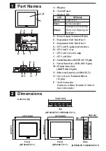
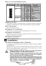
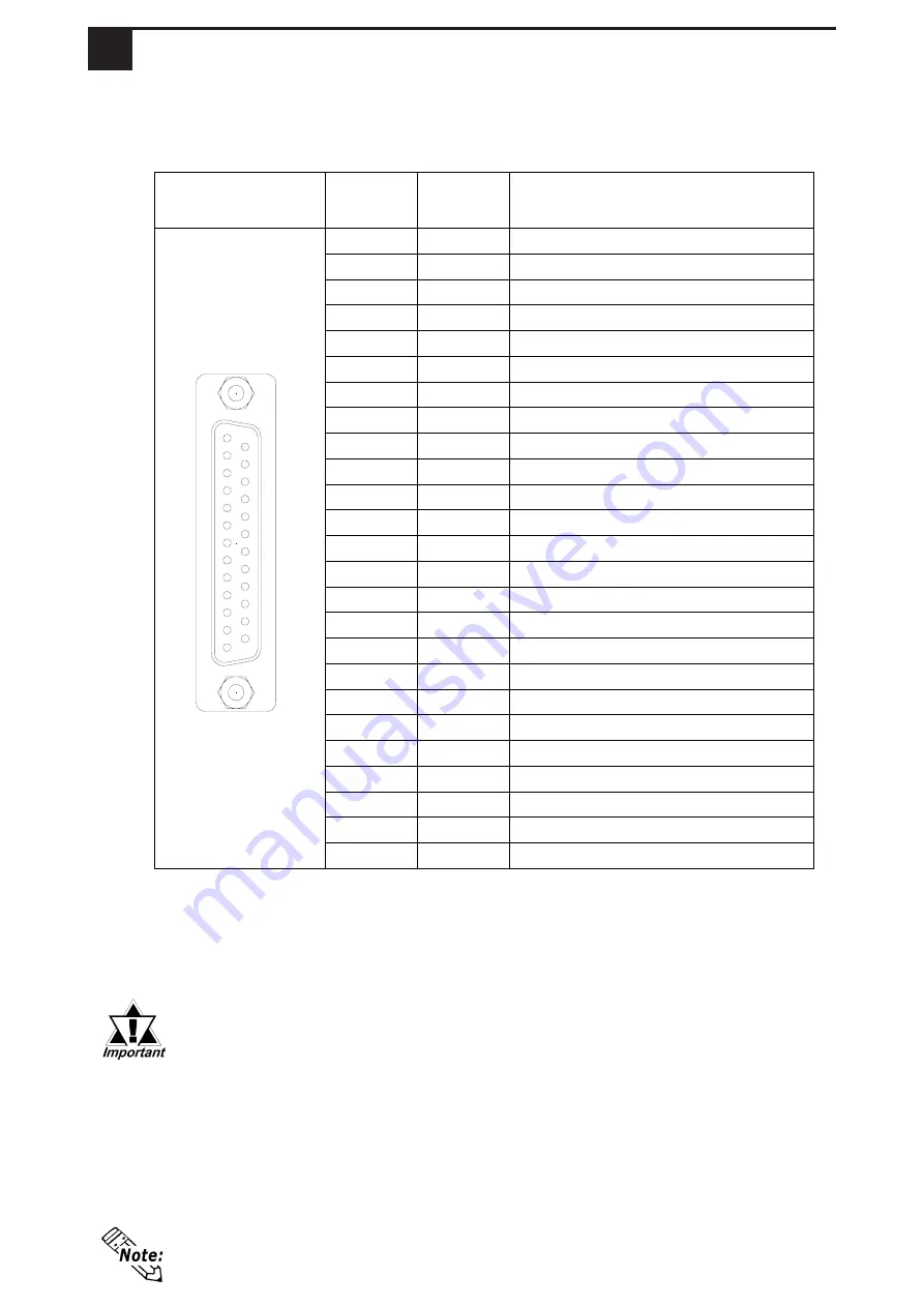
Pin Arrangement
Pin #
Signal
Name
Description
1
FG
Frame Ground
2
SD
Send Data (RS-232C)
3
RD
Receive Data (RS-232C)
4
RS
Request to Send (RS-232C)
5
CS
Clear to Send (RS-232C)
6
DR
Data Set Ready (RS-232C)
7
SG
Signal Ground
8
CD
Carrier Detect (RS-232C)
9
TRMX Termination (RS-422)
10
RDA
Receive Data A (RS-422)
11
SDA
Send Data A (RS-422)
12
NC
No Connection(Reserved)
13
NC
No Connection(Reserved)
14
VCC
5V±5% Output 0.25A
15
SDB
Send Data B (RS-422)
16
RDB
Receive Data B (RS-422)
17
RI
Ring Indicate (RS-232C)
18
CSB
Clear to Send B (RS-422)
19
ERB
Enable Receive B (RS-422)
20
ER
Enable Receive (RS-232C)
21
CSA
Clear to Send A (RS-422)
22
ERA
Enable Receive A (RS-422)
23
NC
No Connection(Reserved)
24
NC
No Connection(Reserved)
25
NC
No Connection(Reserved)
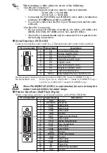
4
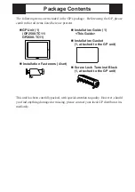
Interfaces
Recommended Connector : Dsub 25 pin plug XM2A-2501 <made by OMRON Corp.>
Recommended Cover
: Dsub 25 pin Cover XM2S-2511 <made by OMRON Corp.>
Jack Screw XM2Z-0071 <made by OMRON Corp.>
Recommended Cable
: CO-MA-VV-SB5P
x
28AWG
<made by HITACHI Cable Ltd.>
• This GP unit’s serial port is not isolated. When the host (PLC) unit is
also not isolated, and to reduce the risk of damaging the RS-422 circuit,
be sure to connect the #7 SG (Signal Ground) terminal.
• Pin #14 (VCC) DC 5V Output is not protected. To prevent damage or unit
malfunction, use only the designated level of current.
• Inside the GP2500/2600 unit, the SG (Signal Ground) and FG (Frame
Ground) terminals are connected to each other.
• When connecting an external device to the GP with the SG terminal,
ensure that no short-circuit loop is created when you setup the system.
Use rough metric type M2.6 x 0.45p threads to hold the cable’s set
(fastening) screws in place.
Serial Interface (HOST-I/F)
This interface is used to connect the GP to the host (PLC), via an RS-232C or RS-
422 cable.
1
14
13
25


