background image

BELL CONTROLLER SPECIFICATIONS

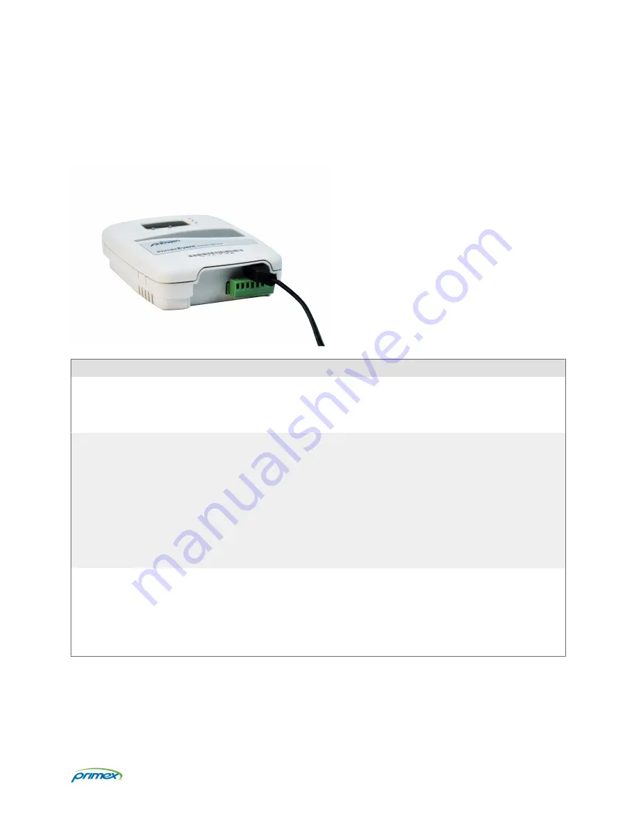
A Bell Controller, part of the OneVue Notify Bell Scheduling system, integrates with an existing public address (PA) or
school bell system to trigger school bells to ring at the times set in the schedules managed in OneVue.

Parameter

Specification

Ratings

3 VDC Relay operation

Normally Closed (NC) & Normally Open (NO) contacts are rated at: resistive load: 8A at
250VAC / 30 VDC | inductive load: 3.5A at 250VAC / 30 VDC

Power

AC power: 5V DC USB Mini B (5 pin) connector interface, 5 ft (1.5 m) cable | Input: 100-240
VAC, 50/60 Hz, 0.4A | Output: 5V DC, 1.0A max. Optional power extension cable: USB power
cable 6.5 feet (2 m), Mini B (5 pin) M and Mini B (5 pin) F connector

Power over Ethernet (PoE): compliant with IEEE 802.3af standard and compatible with
802.3at standard

Battery backup: estimated up to a maximum of 24 hours operating on battery backup
power only. Requires two AA Lithium 1.5V batteries; Energizer® L91 Ultimate Lithium
batteries recommended.

IP Network
Communication

Network LAN port: RJ-45 Ethernet, 10/100 Mbps, 802.3 Ethernet

Network Communication Protocols: Hypertext Transfer Protocol Secure (HTTPS)/TLS 

IP Addressing: Dynamic Host Configuration Protocol (DHCP), static IP addressing

Data Packet Size: typically less than 5 kilobytes (kB)

Page 4

Summary of Contents for OneVue Notify E130

Page 1: ...Notify Bell Controller Installation Guide OneVue Notify Bell Scheduling Publication date April 9 2021...

Page 2: ...e is a trademark of Primex All other trademarks are the property of their respective owners Primex is the leading provider of solutions to automate and maintain facility compliance increase efficienci...

Page 3: ...contents 9 Install requirements 9 Install location guidelines 10 Connect bell controller relays to public address PA or bell system 10 Connect bell controller to dry contact switch for an impromptu be...

Page 4: ...VAC 50 60 Hz 0 4A Output 5V DC 1 0A max Optional power extension cable USB power cable 6 5 feet 2 m Mini B 5 pin M and Mini B 5 pin F connector Power over Ethernet PoE compliant with IEEE 802 3af sta...

Page 5: ...to activate a non scheduled event impromptu bell Connected to an external dry contact closure switch or button On board clock synchronizes its time with an NTP time source to ensure bell schedule acc...

Page 6: ...ch or button to activate a bell manually commonly referred to as an impromptu bell An impromptu bell is a bell event that is not scheduled in OneVue Terminal block connections pin out specifications T...

Page 7: ...than 3 hours It s scheduled to check in hourly For wireless network use a failed check in may be due it is not within range of wireless access point or the wireless signal strength is not adequate for...

Page 8: ...cal Support to assist with troubleshooting the cause of the failure Service buttons A Bell Controller has two service buttons located on the front of the device Button Icon Use Silence During an Alarm...

Page 9: ...kup for up to a maximum of 24 hours 4 3M Dual Lock Tape 2 x 1 strip 1 USB configuration cable supplied with each device order only For use with the Primex Device Configuration software to manually con...

Page 10: ...nes When identifying the mounting location of a bell controller consider the following guidelines Requires a hardwired connection from the bell controller s terminal block to an existing PA or bell sy...

Page 11: ...ch or button to activate a bell manually commonly referred to as an impromptu bell An impromptu bell is a bell ring event that is not scheduled in OneVue The removable terminal connector is provided f...

Page 12: ...he bell controller AC or PoE 10 When power was applied the device automatically initiated a check in to OneVue Verify its LCD displays Signal OK which indicates it successfully checked in to OneVue If...

Page 13: ...bell controller AC or PoE 11 When power was applied the device automatically initiated a check in to OneVue Verify its LCD displays Signal OK which indicates it successfully checked in to OneVue If th...

Page 14: ...an electrical hazard and may damage the device while nullifying its warranty Equipment Precautions To avoid possible electric shock or damage make sure device is not powered during installation or mo...

Page 15: ...or compliance could voice the user s authority to operate this equipment Example use only shielded interface cables when connecting to computer or peripheral devices FCC Warning Any Changes or modific...

Page 16: ...ructure mode Wireless Stations normally scan all Channels looking for an Access Point If more than one Access Point can be used the one with the strongest signal is used This can only happen within an...

Page 17: ...en altered or modified in any way including but not limited to attempted warranty repair other than by Primex or an authorized service partner LIMITATION OF LIABILITY The warranties and remedies conta...

Page 18: ...s technical support services for Primex products If you have purchased Primex products or have a service agreement with a Primex Partner they are your primary contact for all Technical Support inquire...

Reviews: