background image

22

www.pridemobility.com

UK Jazzy 1113/RevF/Apr03

  V .   C O M F O R T   A D J U S T M E N T S

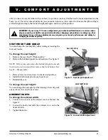
ARMREST ANGLE

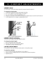
You can increase or decrease the armrest angle to fit your specific needs. See figure 13.

To change the armrest angle:

1. Lift the armrest straight up so that it is perpendicular to the floor.

2. Use a 7/16-in. spanner to loosen the locking nut. See figure 13.

3. Use a  5/32-in. hex key to loosen the adjustment screw.

4. Turn the screw clockwise to lower the front of the armrest and anticlockwise to raise the front of the armrest.

5. Lock the adjustment screw into place by tightening the jam  nut.

ARMREST HEIGHT (OPTIONAL)

Your Jazzy may be equipped with height-adjustable armrests.

To change the armrest height:

1. Remove the ball detent pin from the armrest.

2. Move the armrest up or down to the desired height.

3. Align the holes and reinsert the ball detent pin.

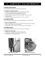
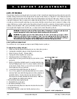
CONTROLLER EXTENSION

The controller can easily slide out away from the armrest, or in toward the armrest.

To extend the controller:

1. Use a 3/16-in. hex spanner to loosen the setscrew. See figure 14.

2. Slide the controller mounting bracket into or out of the armrest to the desired position.

3. Tighten the setscrew.

Figure 14. Underside of Armrest

LOOSEN

THIS

SETSCREW

TO ADJUST

JOYSTICK

Figure 13. Armrest Angle Adjustment

TURN THIS SCREW

TO CHANGE

ARMREST ANGLE

LOCKING NUT

LOCKS

ADJUSTMENT

SCREW

IN PLACE

Summary of Contents for Jazzy 1110

Page 1: ...Unit 106 Heyford Park Camp Road Upper Heyford Oxfordshire OX25 5HA www pridemobility com Owner s Manual ATTENTION Please read the content of your owner s manual before operating your power chair...

Page 2: ...good judgement and or common sense as well as that of your Dealer carer and or healthcare professional Pride is not responsible for injuriesand ordamageresultingfromanyperson sfailuretofollowthewarni...

Page 3: ...3 C O N T E N T S I INTRODUCTION 4 II SAFETY 6 III YOUR POWER CHAIR 13 IV DISASSEMBLY 18 V COMFORT ADJUSTMENTS 21 VI ASSEMBLY 25 VII OPERATION 28 VIII BATTERIES AND CHARGING 40 IX CARE AND MAINTENANC...

Page 4: ...contained on the power chair itself This owner s manual is compiled from the latest specifications and product information available at the time of publication We reserve the right to make changes as...

Page 5: ..._______________________________________________________________________ Phone Number ________________________________________________________________________ Purchase Date ____________________________...

Page 6: ...inwhichyouwill need some practice Simply take your time and you will soon be in full and confident control as you maneuver through doorways on and off of lifts up and down ramps and over moderate terr...

Page 7: ...or damage to your power chair WARNING Inflate your power chair drive tyres from a regulated air source with an avail able pressure gauge Inflating your tyres from an unregulated air source could over...

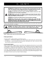
Page 8: ...or descend on your power chair does not exceed 8 7 See figure 1 WARNING Any attempt to climb or descend a slope steeper than 8 7 may put your power chair in an unstable position and cause it to flip r...

Page 9: ...ds Obey the Code of practice for Class 3 vehicle users Failure to heed this warning may result in serious injury and or damage to your power chair NOTE A copy of the Department of Transportation Code...

Page 10: ...and slowly forward to push the door open Or drive your power chair gently and slowly rearward to pull the door open Lifts Modern lifts have a door edge safety mechanism that when pushed reopens the li...

Page 11: ...Avoid putting all of your weight on the footrest Such use may cause the power chair to tip and cause personal injury Positioning Belts YourauthorisedPrideDealer therapist s andotherhealthcareprofessio...

Page 12: ...ter handling WARNING Always protect the batteries from freezing and never charge a frozen battery Charging a frozen battery may result in personal injury and or damage to the battery Preventing Uninte...

Page 13: ...ller Your Jazzy seat may also have some optional accessories attached to it such as a basket a cane and crutch holder or a cup holder See X OptionalAccessories in this manual The power base is the hea...

Page 14: ...standard Recliner High Backwithheadrest Drivetrain Twomotor mid wheel Batteries Two 12 volt U 1 batteries Range Up to 40 km 25 miles BatteryCharger 3 amp Onboard 3 amp Off board optional Electronics 5...

Page 15: ...C H A I R Figure 2 Electronics Tray FRONT BATTERY BOX REAR BATTERY BOX BATTERY CONNECTORS SEAT POSTS MOTOR CONNECTORS Figure 3 Power Base Top View CHARGERINHIBITCONNECTOR 9 PIN CONTROLLER CONNECTOR A...

Page 16: ...harger fuse is located under the electronics tray Aspare fuse is included MainCircuitBreaker Themaincircuitbreakerisasafetyfeaturebuiltintoyourpowerchair Whenthebatteries and the motors are heavily st...

Page 17: ...odisengagethedrive motors 2 TurnthefreewheelleverstowardthefrontoftheJazzytoengage thedrivemotors CAUTION It is important to remember that when your power chair is in freewheel mode the electronic bra...

Page 18: ...fer to III Your Power Chair for specific components weights NOTE During both the disassembly and the assembly of the Jazzy 1113 you may find it helpful to engage the Jazzy drive motors so that it does...

Page 19: ...eatframelatchreleasebuttons one on the front of each seat frame side tube See figure 7 3 Whileyouarepushingbothbuttonsorleverssimultaneously lift up on the front end of the seat frame 4 Pullforwardont...

Page 20: ...ighthandholdingtherightframeassemblyhandle 5 Pullupwithyourlefthandonthefrontframeuntilthelatching mechanismreleases 6 Keep pulling upward with your left hand until the locating pin on the bottom of t...

Page 21: ...HEIGHT AND ANGLE You can change the seat height by either raising or lowering the four seat towers To change the seat height 1 Remove the seat See IV Disassembly 2 Removetheballdetentpinfromeachseatto...

Page 22: ...tightening the jam nut ARMREST HEIGHT OPTIONAL YourJazzymaybeequippedwithheight adjustablearmrests To change the armrest height 1 Remove the ball detent pin from the armrest 2 Move the armrest up or...

Page 23: ...the controller mounting out of the armrest and place it in the other armrest 5 Tightenthesetscrew 6 Connect the controller cable to the armrest with a wire tie See figure 15 FOOTREST HEIGHT Thefootre...

Page 24: ...is by having your authorised Pride Dealer make a small adjustment to the pre programmed deceleration setting in the controller or by moving the seat assembly further to the rear of your power chair An...

Page 25: ...lies together NOTE The front frame should be positioned with the two semicircular notches in the vertical bar facing forward 4 Grasptheotherframeassemblyandlifttheframeassemblyintoanuprightposition 5...

Page 26: ...ables are pinched between the battery or the motor controller box and theframe 4 Connect the 4 conductor power cable connectors from the front and rear battery cases to the electronics tray Push the c...

Page 27: ...ar ofthefrontframe 2 Pushthetabsthroughthematchingnotches 3 Slide the footrest down into place See figure 25 To connect the controller 1 Attach controller to the seat arm See V Comfort Adjustments 2 P...

Page 28: ...6 3 pinchargerinhibit connector Typically theVSIismountedtoone of the armrests and is connected to themotors batteries andtheonboard chargerattheelectronicstray Joystick The joystick controls the dir...

Page 29: ...a fault in the VSI or the electrical system Refer to Trouble Codes n Ripple up and down of lights The joystick was not in the neutral position when the controller was turned on If you get ripple up an...

Page 30: ...information Controller Connector This connects theVSI to the power chair s batteries motors and motor brakes 3 pin Charger Inhibit Connector This connects the VSI to the onboard battery charger This c...

Page 31: ...ry If the connections are good try charging the battery 2 The left motor has a bad connection Check the left motor connection 3 The left motor has a short circuit to a battery connection Contact your...

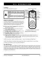
Page 32: ...other components are located inside the power base Remote Plus Master Remote The Remote Plus master remote consists of the following seefigure29 1 joystick 2 keypad 3 controllercommunicationscable 4 o...

Page 33: ...pposite indicator key or the hazard key Light Key Thelightkeyturnstheheadlights taillightsonandoffindependentofotherindicators Hazard Key Thehazardkeytogglesbothindicatorsatthesametime Youcanonlycance...

Page 34: ...key once to keep the setting or push the joystick in the forward or reverse direction The chair will resume operation at the selected speed NOTE We recommend that the first few times you operate your...

Page 35: ...oltage is reduced by 5 volts This reduces your power chair s speed and allows the electrical components to cool down When the temperature returns to a safe level your power chair resumes its normal sp...

Page 36: ...position theelectromagneticbrakewillreleaseandallowthepowerchairtomove Thefurtheryoupushthejoystickfromits neutralposition thefasteryourpowerchairwillmove Whenyoureleasethejoystickandallowittoreturnt...

Page 37: ...ey contactyourauthorisedPrideDealer Toenablethelockoutsystem 1 Holdthemagnetickeyonornearthekeysymbol Thesystemwillbeepandautomaticallyturnoff NOTE None of the remote lights should be lit 2 Presstheon...

Page 38: ...applicable whentheyoccur Actuator Select Keys with Lights If your power chair is equipped with power accessories such as a power seat or power elevating leg rests you can operatethemthroughtheremoteke...

Page 39: ...n fault Check right motor wiring Left park brake fault Check motor brake wiring Right park brake fault Check motor brake wiring Low battery fault Check that the battery wiring is secure Over voltage f...

Page 40: ...omotive type battery charger WARNING Never use an extension lead to plug in your battery charger Plug the charger directly into a properly wired standard wall outlet To charge the batteries by using t...

Page 41: ...e amperage on the charging ammeterdropsasthebatteriesapproachafullcharge Whenthebatteriesarefullycharged theamperagefromthe charger is nearly zero This is how the charger maintains a charge but does n...

Page 42: ...risk of leakage or explosive conditions Why do my new batteries seem weak Deep cyclebatteriesemployadifferentchemicaltechnologythanthatusedincarbatteries nickel cadmium nicads or in other common batt...

Page 43: ...dneverattempttochargeafrozenbattery Acoldor frozen battery should be warmed for several days prior to recharging NOTE If you are storing a Jazzy 1113 for an extended period of time you may wish to blo...

Page 44: ...an authorised Pride Dealer TEMPERATURE Some of the parts of your Jazzy 1113 are susceptible to extreme changes in temperature Always keep your Jazzy 1113 between the temperatures of 0 C 32 F and 50 C...

Page 45: ...ect the controller harnesses Make sure that they are not frayed cut or have any wires exposed See your authorised Pride Dealer if there is a problem with any of these harnesses WEEKLY CHECKS n Disconn...

Page 46: ...s necessary n Checktherearforksfordamageorflutteringwhichindicatesthattheymayneedtobeadjustedorthebearings may need to be replaced See an authorised Pride Dealer for repair n Keep your Jazzy clean and...

Page 47: ...reyoupurchased yourJazzy1113 WARNING To avoid possible injury be sure that the controller s power is turned off and the power chair is not in freewheel mode before performing this procedure WARNING Co...

Page 48: ...battery box one at a time and set them on a solid flat surface See figure 35 4 Unfasten the battery box straps on bottom of box 5 Lift up the top cover 6 Remove the rubber covers off the terminals Un...

Page 49: ...d to provide several thousand hours of operation CAUTION If the brushes become dirty with carbon deposits or wear out a motor will run poorly or notatall If inspectiondeterminesexcessivewearonthebrush...

Page 50: ...ctanauthorised Pride Dealer Whencalling havethemodelnumber serialnumber natureoftheproblem andthetroublecodeif available n Motor noise n Frayed harnesses n Cracked or broken connectors n Uneven wear o...

Page 51: ...o the back of the seat by means of the accessory bracket It can hold a standard size walker CANE AND CRUTCH HOLDER Theremovablecaneandcrutchholderismountedtothebackoftheseatbymeansoftheaccessorybracke...

Page 52: ...ismantle these items renders the guarantee void on that item NOT COVERED UNDER WARRANTY This guarantee does not extend to those items which may need replacement due to normal wear and tear tyres belts...

Page 53: ...UK Jazzy 1113 RevF Apr03 www pridemobility com 53 N O T E S...

Page 54: ...54 www pridemobility com UK Jazzy 1113 RevF Apr03 N O T E S...

Page 55: ...lowing checkmarks indicate that it has been test driven and inspected Quality Control Model 1113 1 In Quality Control FitandFinish Performance Inclusion of all Parts Model __________ Serial __________...

Reviews: