Prestige Solo 175 Installation And Maintenance Manual Download Page 40

34

External Wiring

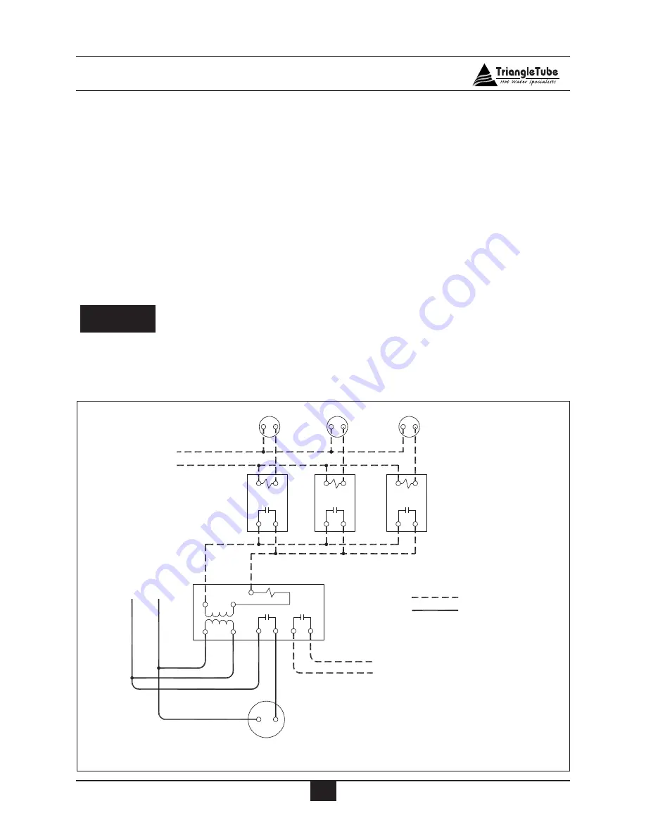
System Circulator - Zone Valve Application

To energize the system circulator shown as
item 12 in Fig. 11 page 22 reference Fig. 21.
Installer to provide a Transformer / Relay such
as Honeywell R8285 or equivalent and Zone
Valves with isolated end switch such as
Honeywell V8043 or equivalent.

Outdoor Temperature Limit

1.  The PRESTIGE  may operate with a vari-

able boiler operating temperature using  the
Triangle Tube outdoor sensor, see pages 48
through 50 for installation and set-up.

If the installer opts for a fixed operating

temperature for the boiler system, the

outdoor sensor is not required and

should not be installed.

Additional 24V Limit Wiring

The PRESTIGE provides 24V terminal con-
nections for  additional limit controls as shown
in Fig. 20 page 32.  These limit terminal con-
nections will provide a "hard" lockout requir-
ing a manual reset of the PRESTIGE control,
or a “soft” lockout in which the PRESTIGE
will automatically reset.

NOTICE

24 V

Transformer

by Others

Honeywell V8043

Zone Valves

or Equivalent

Honeywell R8285D
Transformer / Relay
or Equivalent

 24V Terminal Strip

System Circulator

24V Low Voltage Wiring

120V High Voltage Wiring

Room Thermostats

H

N

120V

R

C

G

1

3 4

6

7

8

To Prestige

Fig. 21: Secondary System Circulator Wiring

Summary of Contents for Solo 175

Page 1: ... 46 Manual Prestige 175 250 If the information in this manual is not followed exactly a fire or explosion may result causing property damage personal injury or death FOR YOUR SAFETY Do not store or use gasoline or other flammable vapors and liquids in the vicinity of this or any other appliance WHAT TO DO IF YOU SMELL GAS Do not try to light any appliance Do not touch any electrical switch do not ...

Page 2: ...tegory IV 6 Methods of Accessing Combustion Air into a Space Category IV 7 Indoor Combustion Air 7 Outdoor Combustion Air 7 8 Combination of Indoor and Outdoor Combustion Air 8 9 Combustion Air and Vent Piping 9 Removal of an Existing Boiler from a Common Vent System 10 Commonwealth of Massachusetts Installation 11 SECTION III UNIT PREPARATIONS Handling Instructions 12 Wall Mounting Installation 1...

Page 3: ...em Piping Zone Valves 20 System Piping Radiant Heating 20 System Piping Special Applications 20 System Piping Multiple Units Installation 20 DHW Piping with PRESTIGE and SMART 21 CH System Piping Diagrams 22 24 SECTION V INSTALLING VENT COMBUSTION AIR CONDENSATE DRAIN Installing Vent and Combustion Air 25 Installing Condensate Drain Assembly 25 26 SECTION VI GAS PIPING Gas Supply Piping Connection...

Page 4: ... Sediment 37 Check and Test Antifreeze 37 Use of Antifreeze in the Boiler System 38 Filling the Boiler System 38 Check Low Water Cut off Device 38 Check for Gas Leaks 39 Check Thermostat Circuit 39 Inspection of Condensate System 39 SECTION X START UP PROCEDURES Final Checks Before Start up 40 PRESTIGE Start up 40 If PRESTIGE Does Not Start Correctly 40 Check the PRESTIGE and System 40 41 Operatin...

Page 5: ...MAINTENANCE PROCEDURES Maintenance Procedures Reported Problems 55 Check Surrounding Area 55 Inspect Burner Area 55 Check System Piping 55 Clean Condensate Drain Assembly 56 Check Ventilation Air Openings 56 Inspect Vent and Combustion Air Piping 56 Check Boiler System 56 Check Expansion Tank 57 Check Boiler Relief Valve 57 Inspection of Ignition Electrode 57 Check Ignition Wiring and Ground Wirin...

Page 6: ...ble of Contents Clean Heat Exchanger 59 Review with Owner 59 Handling Previously Fired Combustion Chamber Insulation 60 REPLACEMENT PARTS Replacement Parts 61 64 PRODUCT SPECIFICATIONS Specifications 65 68 ...

Page 7: ...instructions on installa tion operation or maintenance which are important to equipment but not related to personal injury hazards Indicates recommendations made by Triangle Tube for the installers which will help to ensure optimum operation and longevity of the equipment BEST PRACTICES NOTICE CAUTION WARNING DANGER The following terms are used throughout this manual to bring attention to the pres...

Page 8: ...rvicing the boiler Avoid electrical shock by discon necting the electrical supply prior to performing maintenance CAUTION WARNING WARNING WARNING DANGER Product Safety Information Qualified Installer Prior to installing this product read all instructions included in this manual and all accompanying manuals documents with this appliance Perform all installation steps required in these manuals in th...

Page 9: ... Location Before locating the PRESTIGE check for con venient locations to Heating system piping Venting Gas supply piping Electrical service Ensure the boiler location allows the combus tion air vent piping to be routed directly through the building and terminate properly outside with a minimum amount of length and bends Ensure the area chosen for the installation of the PRESTIGE is free of any co...

Page 10: ...tial garage the following special precautions per NFPA 54 ANSI Z223 1 must be taken Mount the unit with a minimum 18 inches 458 mm above the floor level of the garage Ensure the burner and ignition devices controls are no less than 18 inches 458 mm above the floor level Locate or protect the unit in a matter so it cannot be damaged by a moving vehicle Boiler Freeze Protection Feature The boiler co...

Page 11: ...leakage into the surrounding area Please read the information listed below If contaminating chemicals are located near the area of the combustion air inlet the installer should pipe the combustion air inlet to an outside area free of these chemicals per SECTION V of this installation manual Potential contaminating products Spray cans containing chloro fluorocar bons Permanent Wave Solutions Chlori...

Page 12: ...for the openings is not required Failure to provide or properly size the openings could result in severe personal injury death or substantial property damage Ventilation and Combustion Air Requirements Category IV A Category IV appliance utilizes uncontami nated indoor or outdoor air surrounding the appliance for combustion In order to reduce the potential risks associated with indoor contaminates...

Page 13: ...enings in doors or floors having a total minimum free area of 2 sq in 1000 Btu hr of total input rating of all gas utilization equipment Outdoor Combustion Air Isolating the combustion appliance room from the rest of the building and bring ing in uncontaminated outside air for combustion and ventilation is always preferred Opening Size and Location The minimum dimension of air openings shall be no...

Page 14: ...area of 1 sq in 4000 Btu hr of total input rat ing of all equipment in the enclosure See Fig 3 Where communicating with the out doors is through horizontal ducts each opening shall have a minimum free area of not less than 1 sq in 2000 Btu hr of total input rating of all equip ment in the enclosure See Fig 4 Combination of Indoor and Outdoor Combustion Air Indoor Openings Where used openings con n...

Page 15: ...signed for pressurized venting and condensate The PRESTIGE is certified per ANSI Z21 13 as a Category IV or Direct Vent sealed com bustion appliance A Category IV appliance utilizes uncontamined indoor or outdoor air surrounding the appliance for combustion A Direct Vent appliance utilizes uncontaminated outdoor air piped directly to the appliance for combustion In order to reduce the potential ri...

Page 16: ...at maximum speed Do not operate a summer exhaust fan Close fireplace dampers 4 Place in operation the appliance being inspected Follow the lighting instructions Adjust thermostat so appliance will operate continuously 5 Test for spillage at the draft hood relied opening after 5 minutes of main burner operation Use the flame of a match or can dle or smoke from a cigarette cigar or pipe 6 After it h...

Page 17: ... or equipment at the completion of the installation 4 A metal or plastic identification plate shall be mounted at the exterior of the building four feet directly above the location of vent terminal The plate shall be of sufficient size to be easily read from a distance of eight feet away and read Gas Vent Directly Below Installer must provide tag identification plate and ensure the lettering meets...

Page 18: ...t 2 For applications using wood studs install the bracket using the lag screws provided with the boiler Ensure both lag screws are installed securely in the studs 3 For applications using metal studs install the bracket to the studs using 3 16 toggle bolts and washers 4 DO NOT mount or attempt to mount the wall bracket to hollow sheet rock or lathe walls using anchors Only install boiler to studs ...

Page 19: ... boiler onto the wall bracket 2 Install the boiler making sure the boiler mounting lip located along the upper edge of the rear jacket panel engages the wall mounting bracket Ensure the boiler is seated properly and is secure Hydrostatic Pressure Test Prior to permanently connecting water gas supply or electrical supply perform a pressure hydrostatic test of the boiler water connections to ensure ...

Page 20: ...ximum 30 psig Do not pressurize the boiler and its com ponents above 30 psig Damage to the heat exchanger and the boiler compo nents could occur resulting in personal injury death or substantial property damage 5 Allow the test pressure to remain for 10 minutes Do not leave the unit unattended while pressurized A cold water fill could expand and cause excessive pressure resulting in severe persona...

Page 21: ...Unit Preparations 15 Fig 5 Temporary Hydrostatic Test Piping Fig 6 Pressure Relief Valve Installation ...

Page 22: ...ownward towards the floor at all times The piping should terminate at least 6 inches 153 mm above any drain connection to allow clear visibility of the discharge Should terminate with a plain end not with a threaded end The material of the piping should have a serviceable temperature rating of 250ºF or greater Should not be subject to conditions where freezing could occur Should not contain any sh...

Page 23: ...al codes Boiler System Piping Applications It is recommended on all piping applica tions to utilize a primary secondary pip ing arrangement as a means to provide freeze protection of the boiler which is an integral function of the boiler control and to utilize the full function of the integral boiler circulator while maintaining the minimum flow rate see Graph 1 page 68 For other piping arrangemen...

Page 24: ...r priority and to provide circulation for the freeze protection feature of the boiler control See Graph 1 or Graph 2 on page 68 for pressure drop and min imum flow rate through the boiler Sizing Primary Piping See Fig 9 through 15 pages 21 25 for rec ommended piping arrangements based on vari ous applications Size the piping and system components required in the space heating sys tem using recogni...

Page 25: ...g 8 Near Boiler Piping Closed Type Expansion Tank Fig 7 Near Boiler Piping Diaphragm Expansion Tank 1 System circulator 2 Automatic air vent 3 Air separator 4 Automatic fill valve 5 Diaphragm expansion tank 6 Isolation valve 7 Drain purge valve 8 Tank fitting 9 Close type expansion tank 10 Primary secondary connection 11 Boiler circulator 12 Flow check valve Note Pitch horizontal pip ing upwards 1...

Page 26: ... limit as shown in Fig 14 page 24 This will ensure that the primary supply temperature does not exceed the maximum allowable temperature for the radiant tubing The addition of the high temperature limit is important if the PRESTIGE is connected to a domestic hot water sys tem which requires a high primary sup ply water temperature Size the system piping and circulator to provide the flow needed fo...

Page 27: ...alve 7 Pressure relief valve 8 Drain purge valve 2 1 7 5 6 3 3 4 Supply System System Hot Cold Domestic Domestic Return 8 Fig 9 DHW Piping with a PRESTIGE and SMART The boiler system piping shown in Fig 9 must be a closed system to avoid any oxygen contamination and potential fail ure of the outer tank of the Smart NOTICE ...

Page 28: ...3 Flow check valve 4 Isolation valve 5 Zone circulator 6 Drain purge valve 7 Pressure relief valve 8 Air separator 9 Automatic air vent 10 Diaphragm expansion tank 11 Automatic fill valve Fig 11 CH System Piping Zoning with Zone Valves 1 PRESTIGE boiler 2 CH circulator 3 Flow check valve 4 Isolation valve 5 Zone valve 6 Drain purge valve 7 Pressure relief valve 8 Air separator 9 Automatic air vent...

Page 29: ...nk 11 Automatic fill valve 12 Pressure Differential Valve Fig 13 CH System Piping Single Zone System with Single System Boiler Circulator 1 PRESTIGE boiler 2 CH circulator 4 Isolation valve 5 Zone valve 6 Drain purge valve 7 Pressure relief valve 8 Air separator 9 Automatic air vent 10 Diaphragm expansion tank 11 Automatic fill valve Note Verify CH circula tor is properly sized to overcome the sys...

Page 30: ...be used in lieu of zone valves 1 PRESTIGE boiler 2 CH circulator 3 Flow check valve 4 Isolation valve 5 Zone valve 6 Drain purge valve 7 Pressure relief valve 8 Air separator 9 Automatic air vent 10 Diaphragm expansion tank 11 Automatic fill valve 12 System circulator 13 High temperature limit control Fig 14 CH System Piping Radiant Low Temp Heating ...

Page 31: ...8 9 2 12 Max 1 Boiler circulator 2 Isolation valve 3 Flow check valve 4 System circulator 5 Drain purge valve 6 Automatic air vent 7 Air separator 8 Diaphragm expansion tank 9 Automatic fill valve Fig 15 Multiple Prestige Boiler Piping Primary Secondary Piping using Pre Fab Manifolds ...

Page 32: ...on nut and rubber seal from the drain outlet 4 Using 3 4 x 2 flexible PVC tube provid ed slide the compression nut and rubber seal over the pipe The use of 3 4 PVC or CPVC pipe is also acceptable If 3 4 pipe is used deburr and chamfer pipe to allow mat ing onto the drain assembly 5 Thread the rubber seal into the compres sion nut to ease installation of the pipe to the drain assembly 6 Seat the pi...

Page 33: ...ondensate The condensate should not be subject to conditions where freezing could occur If the con densate is subjected to freezing or becomes obstructed it can exit from the heat exchanger resulting in potential water damage to the boiler and sur rounding area CAUTION Condensate Drain Assembly Slip Ring with rubber seal hand tight only 3 4 PVC or CPVC Piping to Drain Compression Nut with Rubber S...

Page 34: ...onnect the PRESTIGE and its gas valve from the gas supply piping during any pressure test greater than 13 w c Do not check for gas leaks with an open flame Use a gas detection device or bub ble test Failure to check for gas leaks can cause severe personal injury death or substantial property damage 7 Use pipe dope compatible with natural and propane gases Apply sparingly only to the male threads o...

Page 35: ... building 2 Install 100 lockup gas pressure regulator in the gas supply line if inlet pressure can exceed 13 w c at any time Adjust the lock up pressure regulator for 13 w c maximum DO NOT adjust or attempt to measure gas valve outlet pressure The gas valve is factory set for the correct outlet pres sure This setting is suitable for natural gas and propane and requires no field adjustment Attempts...

Page 36: ...ory set for the correct outlet pres sure This setting is suitable for natural gas and propane and requires no field adjustment Attempts by the installer to adjust or measure the gas valve outlet pressure could result in damage to the valve causing potential severe personal injury death or substantial property damage Prior to start up ensure the unit is set to fire propane Check the rating label fo...

Page 37: ...uctions 1 Locate the wiring tool on the PRESTIGE just below the the MCBA control in a plas tic bag 2 Locate the terminal blocks on the PRES TIGE below the MCBA control The 120V Terminals are located on the left set of Terminal Blocks The 24V Terminals are located on the right set of terminal blocks 3 Carefully pull down on the lower half of the terminal block to remove 4 Hook the wiring tool into ...

Page 38: ...32 Internal Wiring Fig 20 Prestige SOLO 175 and Solo 250 Boiler Factory Wiring ...

Page 39: ...Connect the DHW circulator to the 120V terminal strip on the wiring panel below the PRESTIGE control module as shown in Fig 20 page 32 2 Connect the DHW thermostat aquastat to the 24V terminal strip on the wiring panel located below the PRESTIGE control mod ule as shown in Fig 20 page 32 Route all wiring through the provided open ings in the bottom jacket panel Allow enough wire for access panel t...

Page 40: ...ed operating temperature for the boiler system the outdoor sensor is not required and should not be installed Additional 24V Limit Wiring The PRESTIGE provides 24V terminal con nections for additional limit controls as shown in Fig 20 page 32 These limit terminal con nections will provide a hard lockout requir ing a manual reset of the PRESTIGE control or a soft lockout in which the PRESTIGE will ...

Page 41: ...minal Strip H N High Voltage 120 V A C 24 V A C Room Thermostat Room Thermostat Zone 1 Zone 2 Additional zones Additional zones may be added as shown above Transformer Power Zone Valve Zone Valve Isolation relay 7 8 Use isolation relay on 3 wire zone valve with non isolated end switch Transformer and the Prestige MCBA control can burn out if isolation relay is not used 4 Wire Zone Valve 3 Wire Zon...

Page 42: ...al zones may be added as shown above 7 8 6 2 1 4 3 5 6 2 1 4 3 5 T T T T Fig 23 Field wiring with zone circulators Thermostat Zone 1 Zone 1 Circulator 120 VAC N To Prestige 24V Terminal Strip Zone 2 Circulator Zone 3 Circulator Thermostat Zone 2 Thermostat Zone 3 R C T1 T1 T2 T2 T3 T3 C3 C3 C2 C2 C1 C1 PR PR X2 X1 L1 L2 ZC H 7 8 Fig 24 Typical Zone Relay Panel Wiring ...

Page 43: ...wimming pool or spa directly Maintain the chlorine level of the water at lev els considered safe for drinking Flush Boiler and Domestic System to Remove Sediment The installer must flush the boiler system to remove any sediment to allow proper operation of the PRESTIGE Flush the systems until the water runs clean and is free of sediment For boiler zoned systems each zone should be flushed through ...

Page 44: ...he bottom of the unit and any manual or auto matic air vent in the system 2 Open all system isolation valves 3 Fill the boiler system to correct system pressure Correct pressure will vary with each application Typical residential system fill pressure is 12 psi System pressure will increase when system temperature increases Operating pressure of the system should never exceed 25 psi 4 Purge air and...

Page 45: ... and check the voltage reading across the wire ends There should NEVER be voltage measured at the wire ends If voltage is measured at the panel under any condition check and correct the external wiring In systems using 3 wire zone valves backfeed of voltage to the unit is a com mon problem Use an isolation relay to prevent voltage from the external circuit entering the PRESTIGE control panel Recon...

Page 46: ...ervice switch to the unit in the ON position 2 Read and follow the Operating Instructions outlined on page 42 If PRESTIGE Does Not Start Correctly 1 Verify CH parameter 2 and DHW para meter 3 systems are turned ON or set to 01 Read the Boiler Display Standby and Parameter Section of the manual starting on page 45 for more information 2 Check for loose electrical connections blown fuse external or ...

Page 47: ...ce the boiler into high fire mode reference page 45 the combustion reading should be within the range listed in Table 2 The CO level should not exceed 100 ppm when combustion is correct The combustion levels should be mea sured at high firing rate refer to page 45 of the PRESTIGE control section on how to set the firing rate If the combus tion levels are not within the range given in Table 2 for t...

Page 48: ...nce below and call your service technician or gas supplier 11 Replace the front jacket panel Make sure the panel is seated firmly in place and all mounting screws are tightened If you do not follow these instructions exactly a fire or explosion may result causing property damage personal injury or loss of life 1 Set the room thermostat to lowest setting 2 Turn the service switch on the PRESTIGE co...

Page 49: ...g 3 Turn off power to the boiler wait a few seconds and turn on power to the boiler 4 The following displays should occur A140 Self check on power up 0140 No call for heat 5 Initiate a call for heat by raising the set point of the room thermostat to the highest setting The following display should occur 1140 This is the prepurge cycle The boiler blower and the CH Central Heating circulator become ...

Page 50: ...cable 1 As outlined in the verification for space heating repeat STEPS 2 through 4 2 Raise the DHW aquastat setting to initiate a call for heat As in the space heating opera tion the display should show 1180 The prepurge cycle The boiler blower and DHW circulator become ener gized and the 10 second pre purge cycle begins 2180 The boiler will begin the ignition sequence The same sequence of establi...

Page 51: ...est mode high limit will function boiler circulator will function domestic circulator will not function the test mode will time out in approxi mately 10 minutes TO TEMPORARILY PLACE THE BURN ER INTO LOW FIRE TEST MODE press the MODE button until StbY is displayed Then press and hold both the mode and but ton simultaneously until the first digit flashes L Press and hold the and button simulta neous...

Page 52: ... Burner will remain OFF for a 10 minute period Burner will recycle increasing waiting period 1 minute for a max 15 minutes Factory supplied LWCO pressure device or external limit terminals 15 16 is OPEN Burner off for 150 seconds auto reset 0 1 180 180 180 180 180 180 180 180 180 180 2 3 4 5 6 7 8 9 18 b 19 b 24 b 25 b 26 b 2 Display Boiler function No blower signal Blower signal present Burner wi...

Page 53: ... Information Information mode To switch from STANDBY mode to INFOR MATION mode press MODE twice Press STEP until the system displays the infor mation you need The point located behind the first position flashes to indicate that the boiler is in INFO mode If STEP is pressed after parameter 9 the dis play will show A 32 NFO I ARA P ARA P MODE NFO I MODE Key Display Pressing MODE once Pressing MODE t...

Page 54: ...ternal control failure E E 02 03 04 08 09 E E E Display Hard Lockout Internal control failure 05 E Internal control failure 06 E Internal control failure 07 E Flame detected prior to burner startup E 00 Internal control failure External limit terminal 13 14 control is OPEN Blower signal does not reset to zero No blower signal present Supply temperature sensor is short circuited 11 12 15 16 29 28 E...

Page 55: ...crews provided Wiring the Sensor 1 Unthread the sealing nut and remove the sealing gasket from the sensor enclosure 2 Route 18 AWG 2 wire cable or similar wire cable through the sealing nut and gasket Connect the wire ends to the sensor termi nals 1 and 2 3 Re insert the sealing gasket and tighten the sealing nut to the sensor enclosure 4 Route the sensor cable back to the PRES TIGE boiler ensurin...

Page 56: ...tically detect the presence of the outdoor sensor once it is connected to the outdoor sensor terminals on the 24V terminal strip see unit wiring diagram Fig 20 page 32 With the outdoor sensor present the boiler target temperature will default to a temper ature as defined by the outdoor air reset As the outdoor temperature drops the boil er target temperature will increase The boiler target tempera...

Page 57: ...ed for 140ºF target temperature at 0ºF outdoor air temperature Table 3 Outdoor Air Temperature Reset Example 90 20 60 100 140 180 70 68 50 30 10 0 10 86 Boiler Temperature F Outdoor Air Temperature F Parameter 4 Set Point Graph 1 Outdoor Air Temperature Reset Curve Example Outdoor Boiler Target Temp Temperature Based on Outdoor Temp 0ºF or Lower 140ºF 23ºF 122ºF 40ºF 108ºF 68ºF or Higher 86ºF ...

Page 58: ...ied as outlined on page 41 c Measured the rate of input on Natural Gas as outlined on page 41 c Checked the incoming gas pressure to the Prestige to ensure a minimum pressure of 5 w c during flow conditions to all gas appliances and a maximum pressure of 13 w c during non flow conditions for Natural and Propane c Adjusted balancing valves and system limit controls to provide design temperatures to...

Page 59: ...eted Check out procedures have been followed and completed Information regarding the unit and installation received and left with owner maintenance personnel Installer Information Company Address Address Phone Number Btu hr ____________________________________________________________________ ____________________________________________________________________ ______________________________________...

Page 60: ...itional items if combustion or performance is poor Clean heat exchanger and flue ways Remove burner assembly and clean burner head using compressed air only Once the maintenance items are completed review the service with the owner Owner Maintenance Periodically Check the area around the unit Check and remove any blockage from the combustion air inlet and ventilation open ings Check the temperatur...

Page 61: ...ree of combustible flammable mate rials or flammable vapors or liquids Remove immediately if found Verify that combustion air inlet area is free of any contaminates Refer to the list of potential materials listed on page 5 of this manual If any of these products are in the area from which the unit takes its combustion air they must be removed immediately or the combus tion air intake must be reloc...

Page 62: ...bustion air intake are free of debris and obstructions Inspect Vent and Combustion Air Piping Visually inspect the venting system and com bustion air piping for blockage deterioration or leakage Repair any deficiencies Verify that the combustion air inlet piping is connected sealed and properly supported Failure to inspect the vent system and combustion air inlet piping and to have any conditions ...

Page 63: ... the warning tag of the valve Before manually operating the pressure relief valve ensure the discharge piping is directed to a suitable place of disposal to avoid a potential scald hazard The dis charge piping must be full size without restriction and installed to permit com plete drainage of both the valve and line If after closing the valve the valve fails to seat properly or continually weeps r...

Page 64: ... head Remove the venturi and gas valve assembly from the blower Use the vacuum cleaner or compressed air to clean the interior of the blower assembly Inspect the blower blades to ensure they are clean and not damaged Re assemble the venturi and gas valve onto the blower Ensure the venturi gasket is in good condition and positioned correctly Re assemble the burner head onto the mount ing plate Ensu...

Page 65: ...t exchanger flue ways Do not use any solvent 7 Reinstall the burner assembly burner plate and combustion chamber insulation onto the heat exchanger Ensure the plate gasket and combustion chamber insulation is in place and not damaged See warning on page 60 8 Tighten the mounting nuts onto the burner plate Do not use excessive force in tight ening 9 Reconnect the gas piping and check for leaks 10 C...

Page 66: ...approved respirator which meets OSHA requirements for cristobalite dust similar to N95 Contact NIOSH at 1 800 356 4676 or on the web at www cdc gov niosh for latest recommen dations 2 Wear long sleeved loose fitting clothing gloves and eyes protection 3 Assure adequate ventilation 4 Wash with soap and water after contact 5 Wash potentially contaminated clothes separately from other laundry and rin...

Page 67: ... 2 PSJKT03B Base Panel 3 PSJKT01F Front Jacket Panel 4 PSJKT02R Rear Jacket Panel 5 PSJKT01S Side Jacket Panel Left and Right 6 PSJKT03T Top Jacket Panel 7 PSJKT04T Top Jacket Panel Access 8 PSJKT03 Control Cover Panel 9 PSRKT21 Wall Mounting Bracket with Hardware Fig 26 Prestige Jacket Components ...

Page 68: ... Body SOLO 250 2 PSRKIT27 Vent Outlet Adapter 3 PSRKIT03 Combustion Air Inlet Adapter 4 PSRKIT04 NTC Sensor NTC1 NTC2 and NTC5 5 PGRKIT20 LWCO Pressure Device 6 PSRKIT05 Condensate Drain Assembly 7 PSRKIT28 Boiler Piping Return Assembly 8 PSRKIT29 Boiler Piping Supply 9 Pressure Gauge Fitting 1 Fig 27 Prestige Internal Components ...

Page 69: ...Blower with Gasket 5 PGRKIT01 Gas Valve 6 Venturi 051 SOLO 250 Venturi 052 SOLO 175 7 PSRKIT14 Ignition Cable 8 PSRKIT15 Igniter with Gasket 9 PSRKIT16 Sight Glass Assembly Glass Gasket and Bracket 10 Propane Orifice Not Shown 11 Burner Plate Gasket Not Shown 12 PSRKIT15 Gas Valve Rectifier Plug Not Shown Fig 28 Prestige Burner Components Replacement Parts ...

Page 70: ...cription 1 PSRKIT18 Prestige Control Module 2 PSRKIT19 Transformer with Surge Protection 3 PSRKIT20 Prestige Control Module Display 4 PSRKIT17 Pressure Gauge Not shown 3 Fig 29 Prestige Electronic Components Replacement Parts ...

Page 71: ...65 Product Specifications Front View Prestige SOLO 175 250 ...

Page 72: ...66 Product Specifications Side View Prestige SOLO 175 250 ...

Page 73: ...city of the PRESTIGE SOLO 175 250 is based on the test require ments of the U S Department of Energy Note 2 The IBR rating is based on a piping and pick up allowance of 1 15 This allowance should be sufficient for the standard radiation requirements for a building load Note 3 Based on the given AFUE the PRESTIGE SOLO 175 250 meets the energy efficiency guidelines established by Energy Star Note 4 ...

Page 74: ...duct Specifications Graph 1 Pressure Loss Through Boiler Grundfos Circulators Note Minimum allowable flow rate at full input 6 gpm SOLO 175 9 gpm SOLO 250 Graph 2 Pressure Loss Through Boiler Taco Circulators ...

Page 75: ...cleaning and self descaling Computerized sizing available from Triangle Tube Phase III Available in capacities from 25 000 BTU hr to 5 000 000 BTU hr Phase III Indirect Fired Water Heaters Freeway Center 1 Triangle Lane Blackwood NJ 08012 Tel 856 228 8881 Fax 856 228 3584 http www triangle tube com E mail Info triangle tube com Member of Group Heat Master Series Water Heaters Stainless steel const...

Reviews: