35
8.0
External Wiring
loop. The boiler supply temperature sensor
will continue to be used as a high temperature
limit.
Locate the system temperature sensor
where it can accurately measure the sup-
ply temperature to the heating system.
Inaccurate system temperature readings
could lead to overheating or under heat-
ing resulting in property damage.
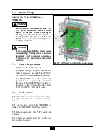
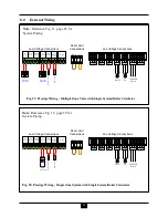
1. Connect the system temperature sensor to
the low voltage terminal strip on the wiring
panel below the PRESTIGE control mod-
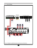
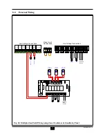
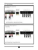
ule, as shown in Fig. 19 on page 31 & Fig.
22 on page 33.
8.12 Cascade Wiring
The ACVMax control includes the ability to
operate up to six boilers together as one with-
out the need for external controllers. Consult
the PRESTIGE ACVMax Control Supplement
for more information.
8.13 Modbus Wiring
The ACVMax control includes the ability to
communicate with building management sys-
tems (BMS) through a Modbus interface.
Consult the PRESTIGE ACVMax Control
Supplement for more information.
CAUTION


