128-9310
19of 30
19
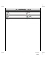
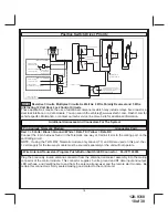
4 Pin Shock Sensor:
(White Connector)
Part # 1122591
The Red (+12 volt), Black (ground), Blue (pre-detect) and Green (full trigger when armed) wires loaded
into the white connector shell are the inputs/outputs of the shock sensor. Route the 4 wire harness from
the shock sensor to the remote start control unit and plug the 4 pin white connector into the mating 4 pin
connector shell of the control module.
NOTE:
While operating under the control of the remote start unit the shock sensor will be shunted,(by-
passed). Once the remote start shuts down, the shock sensor will be re-enabled.
TIMED START PROGRAM:
The Remote Start unit has the ability to start the vehicle automatically at timed intervals. This feature is
useful in extremely cold climates where starting the engine is the only means to keep the battery charged
and fluids warm. The operator has the option to have the unit start every 2 or 4 hours for a maximum of
48 hours. Factory preset is to start at 4 hour intervals. To select 2 or 4 hour automatic start timer:
1. Start By Holding the Push Button Switch found on the windshield mount receiver on.
2. While Holding the Push Button Switch Turn The Ignition Switch On Then Off
3a) Within 10 seconds of turning the ignition switch off, Release and then Push On and release the
Push Button Switch 2 times holding it on the second time until the siren and or lights flash and chirp 2
times indicating that the 2 Hour Start Interval has successfully been set. or
3b) Within 10 seconds of turning the ignition switch off, (Step 2) Release
and then Push On and release the Push Button Switch 4 times holding it on the fourth time until the si-
ren and or lights flash and chirp 4 times indicating that the 4 Hour Start Interval has successfully been
set.
NOTE: Once selected, 2 or 4, this timer interval will remain in memory until it is manually changed. To
change, the above sequence will have to be followed.
TIMED START OPERATION:
To begin the start timer, within 10 seconds of turning off the ignition switch, activate the RF command
to start 2 times. (Press the start button four times). The lights will flash and the siren will chirp 4 times.
Indicating timed interval mode has been initiated. The vehicle will automatically start every 2 or 4 hours
as programmed. To cancel the timed start mode start the vehicle either by RF or by the ignition key.
TEMPERATURE START:
When Temperature Start, (Bank 3 feature #13), is selected on, the temperature start mode can be acti-
vated from the transmitter by pressing the Lock + Option button simultaneously. Once activated, the unit
will start 1 time if the vehicle temperature reaches "0* " and then will run the allotted time.
DIESEL ENGINE SETTINGS:
NOTE:
When selecting Diesel operation, (Bank 3 Feature #12), over gasoline, the only change is to
the ignition circuits. When Diesel is selected, the ignition circuits will power up 10, 15, or 20 seconds
before the start circuit. The intent of this feature is to allow the glow plug warming required by some
diesel engines. If your vehicle is a instant start diesel, it is not necessary to activate this feature.
ALSO:
When selecting Diesel mode, be certain that the intended vehicle has a true tach reference and
be certain to connect the tach input wire. Also note, if the "Diesel Wait to Start" input is connect-
ed,(Green/Yellow) this wire will take precedence over the Diesel selection of bank 3 feature 12.
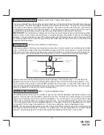
4 PIN IN VEHICLE DATA BUS PORT (DBI Port)
(Connector Port)
The 4 pin port located on the side of this module is for proprietary Audiovox data bus interface modules.
These modules are used to access a variety of features in the vehicle which can be as simple as door
trigger inputs, to more complex door locks outputs, or transponder interfaces for remote starting. DO
NOT connect anything to this port other than the Audiovox IDB modules or damage to the Remote Start
module will occur. All installation instructions for the IDB modules will be packaged with the individual
component along with the proper 4 pin wiring harness requires to access the data transmit & receive as
well as the proper voltage levels for the interface.
Summary of Contents for APS-997EC
Page 31: ...128 9310 31of 30 31...
Page 32: ...128 9310 32of 30 32...

