128-9310
12of 30
12
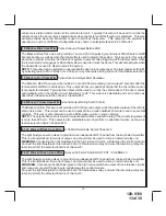
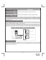
11 DK. Green Wire:
(-) Instant Trigger Input
The Dark Green wire is the instant on ground trigger input wire. This wire must be connected to the hood
pin switch previously installed, and the trunk pin switch where used.
NOTE:
This wire will be shunted when remote control channel 3 is accessed, (trunk release). This wire
will remain shunted all the while there is ground present and for 5 seconds after the ground is removed.
This allows the operator to open the trunk via the remote transmitter without having to first disarm the
alarm system.
12 Empty Cavity / No Connection
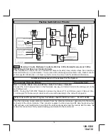
13 LT. Green Wire:
(-) Instant Trigger Zone 1
This is a instant on ground trigger input intended for the connection of optional triggering devices. The
ground trigger output wire of motion detectors, microwave detectors, or glass break detectors, can be
connected to this Light Green trigger input wire.
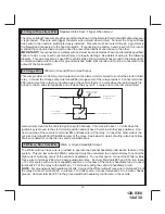
14 Dark Blue Wire: (-)
300mA Pulsed Channel 3 Output (Trunk)
The Dark Blue wire supplies a 300mA ground pulsed output whenever channel three of the receiver
is accessed. Pressing the pre-programmed transmitter button for three seconds will access chan-
nel three. This is a low current output and must be connected to a relay to supply power to the trunk
release or the circuit you wish to control. Connect the Dark Blue wire to terminal # 86 of a 30 amp
automitive relay Connect terminal # 85 of the relay to a fused + 12 volt source. Connect the common,
normally open, and normally closed contacts of the relay to perform the selected function of channel 3.
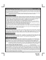
15 Green w/ Black trace Wire:
300mA Pulsed Channel 4 Output
The Green w/ Black Trace wire supplies a 300 mA switched output whenever channel four of the receiver
is accessed. Pressing the pre-programmed transmitter button(s) will provide a 1 second pulse to channel
four This is a low current output and must be connected to a relay to supply power to the device you intend
to control. Connect Green w/ Black Trace wire to terminal #86 of a 30 amp automotive relay. Connect
terminal #85 of the relay to a fused + 12 volt source. Connect the common, normally open, and normally
closed contacts of the relay to perform the selected function of the channel 4 output.
NOTE:
This wire also can be used for defrost activation as dictated by the setting of feature # 1 of Bank 3.
Anytime the vehicle is running under control of the Remote Start and Channel 4 is activated, then depen-
dent on the selection of this feature, Green/Black will be activated for a 1 second pulse, or for 10 minutes.
Note
this wire will, as a defrost output, only operate when running under control of the remote start,,,it
will not operate when the vehicle is running under the control of the ignition key.
When the key & remote start are off, the output will operate as indicated above.
16 DK. Blue w/ Red trace Wire :
Delayed 300 mA PULSED OUTPUT / CHANNEL 7
The light blue/red wire pulses to ground via an independent RF channel from the keychain transmitter.
This is a transistorized, low current output, and should only be used to drive an external relay coil.
WARNING:
Connecting the light blue/red to the high current circuits, will damage the control module.
Connect the Dark Blue/Red to terminal 86 of a 30 A automotive relay, and wire the remaining relay con-
tacts to perform the selected function of channel 7.
17 Black w/ Light Green trace Wire:
Pulsed Ground Output After Start
The Black w/ Light Green Trace wire will provide a 1 second 300mA pulsed ground output after the
Summary of Contents for APS-997EC
Page 31: ...128 9310 31of 30 31...
Page 32: ...128 9310 32of 30 32...


